I wrote a post a while ago about how to prepare solid Zinc Bromide from Zinc Sulfate and Sodium Bromide through the use of water and isopropyl alcohol. However, this method has substantial issues when it comes to its practical implementation, as taking ZnBr2 out of solution is an arduous process that can also be dangerous due to the often aggressive splashing of hot concentrated ZnBr2 solutions. Taking the Zinc Bromide to a solid also seems unnecessary given that in the end we want to end up with ZnBr2 solution for batteries. What if we could just mix Zinc Sulfate and Sodium Bromide and somehow end up with a solution known Zinc Bromide concentration after precipitating the Sodium Sulfate? I will tell you how to do just that in this post.
The solubility of Zinc Bromide is exponentially greater than that of Zinc Sulfate, Sodium Bromide and Sodium Sulfate so mixing a solution of Sodium Bromide and Zinc Sulfate generates a concentrated solution of Zinc Bromide and precipitates almost everything else. At 0C the solubility of ZnBr2 is still 311g/100mL while that of Na2SO4 drops to 4.76g/100mL and that of ZnSO4 drops to nearly 0. It is important to keep an excess of Zinc Sulfate in the reaction though as the solubility of NaBr is still quite high at 0C, reaching more than 79g/100mL.
In order to carry out this synthesis I have followed this process:
- In a 250mL clean beaker, weight 45g of Zinc Sulfate Monohydrate
- Add 51g of Sodium Bromide
- Add 100mL of distilled water (it’s important to use distilled water)
- Heat the mixture with stirring till boiling starts or everything dissolves.
- Let the mixture cool until it reaches room temperature
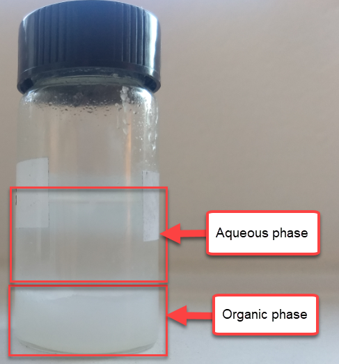
- Optionally you can add 10mL of isopropanol here, which greatly reduces the Sodium Sulfate contamination. (rubbing alcohol works just fine)
- Place in a freezer for 24 hours.
- Filter the solution to remove all Sodium Sulfate and unreacted Zinc Sulfate.
- If isopropanol was added, boil the solution until all the alcohol is removed.
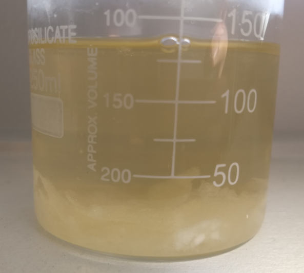
What you are left with is a concentrated solution of ZnBr2 of unknown concentration. Since we do not know how much the volume of the solution changed due to the reaction and some volume of solution is always left wetting the remaining solid, we cannot accurately determine the molarity of the solution from the things we added and what we obtained. We need to perform some measurements to get an idea about how much ZnBr2 we have in solution.
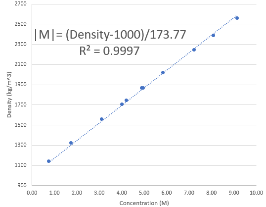
However, since this is a mostly ZnBr2 containing solution – with likely less than 5% of the salt weight being from sodium sulfate contamination – we can estimate the amount of Zinc Bromide by measuring the density of the solution and looking at experimental results showing the density variations of pure Zinc Bromide solutions. Using the experimental data from this paper from 1994, I was able to create the above graph, which allows you estimate how concentrated your Zinc Bromide solution is. Note that you should input the density in the equation expressed in kg/m^3.
In order to measure the density of the solution, I used a 10mL pycnometer, which you can buy here for a low price. A pycnometer allows you to very accurately determine the density of a solution since its volume is exact. By weighting the empty pycnometer and the filled pycnometer and then dividing the difference of this weights by 10 (volume of the pycnometer), you can obtain the measurement in g/mL which you can multiply by 1000 to get the value in kg/m^3.
Once you know the approximate concentration of your solution you will know how much you would need to dilute the solution to arrive at your desired concentration. Solutions produced with the above method are bound to be in the 4-7M region, so you will probably need to dilute them to arrive at a concentration that is better suited for the ZnBr2 batteries. With this information you can now prepare ZnBr2 solutions for your batteries without the need to prepare pure solid Zinc Bromide, have to deal with aggressively splashing solutions or have to go through any further purification processes.
Since Zinc Sulfate Monohydrate and Sodium Bromide are both widely available almost anywhere for really low prices, this should allow a lot of people to experiment with these batteries with low costs, yet retain the ability to understand what the concentration of their electrolyte is.