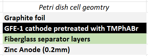
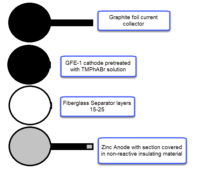
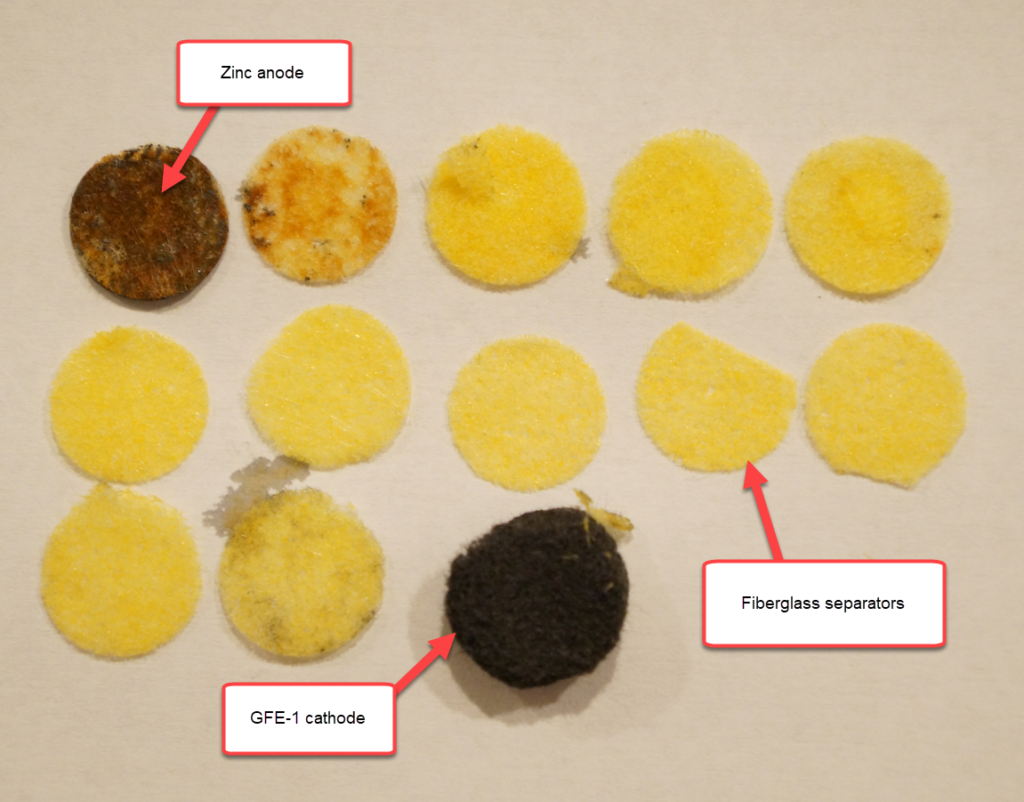
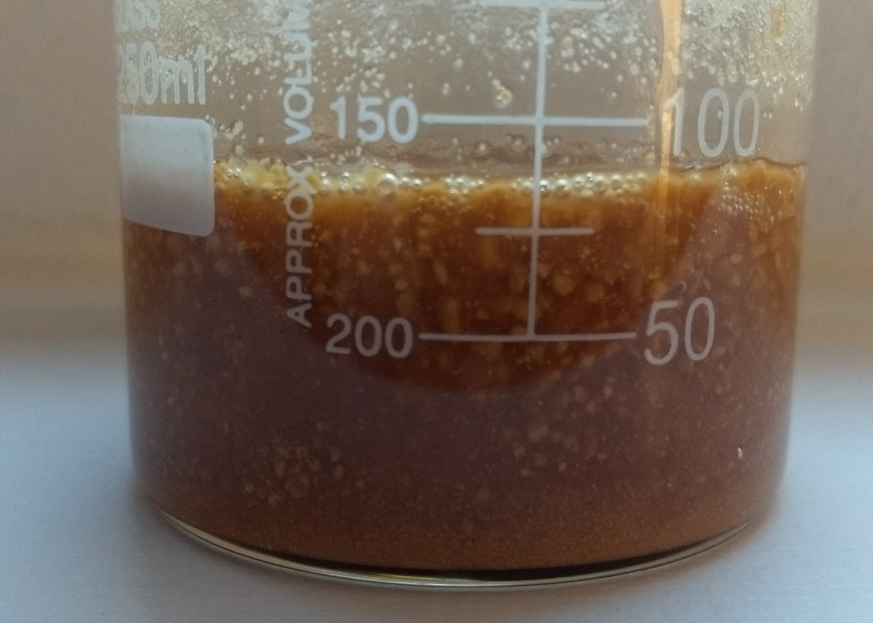
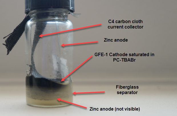
Almost all of my efforts in the construction of Zn-Br batteries have focused on the used of sequestering agents in order to enhance the performance of the batteries and obtain higher energy densities and lower self-discharge rates. However, a couple of people have asked me what the results of a “minimal architecture” Zinc-Bromine battery would be with my current battery design. I therefore put together a battery using a 0.2mm Zn anode, 15 layers of fiberglass separator, a GFE-1 cathode without any pretreatment and a 2.7M ZnBr2 electrolyte with 1% Tween20 (which is needed to prevent dendrite formation).
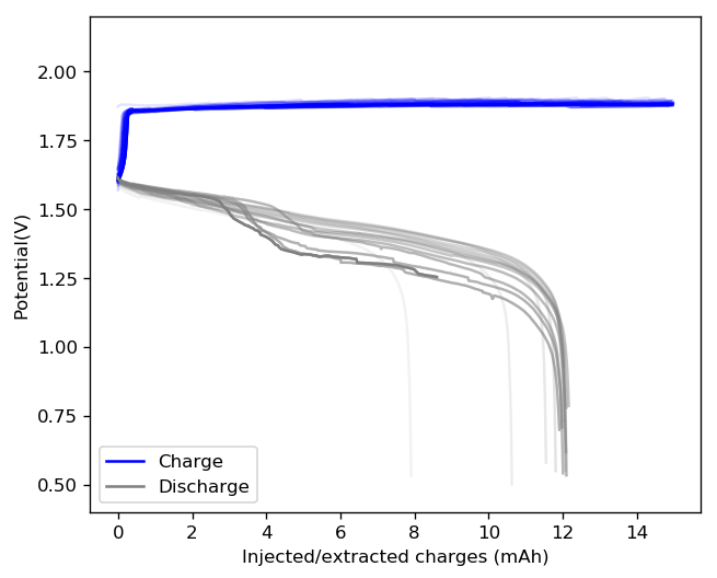
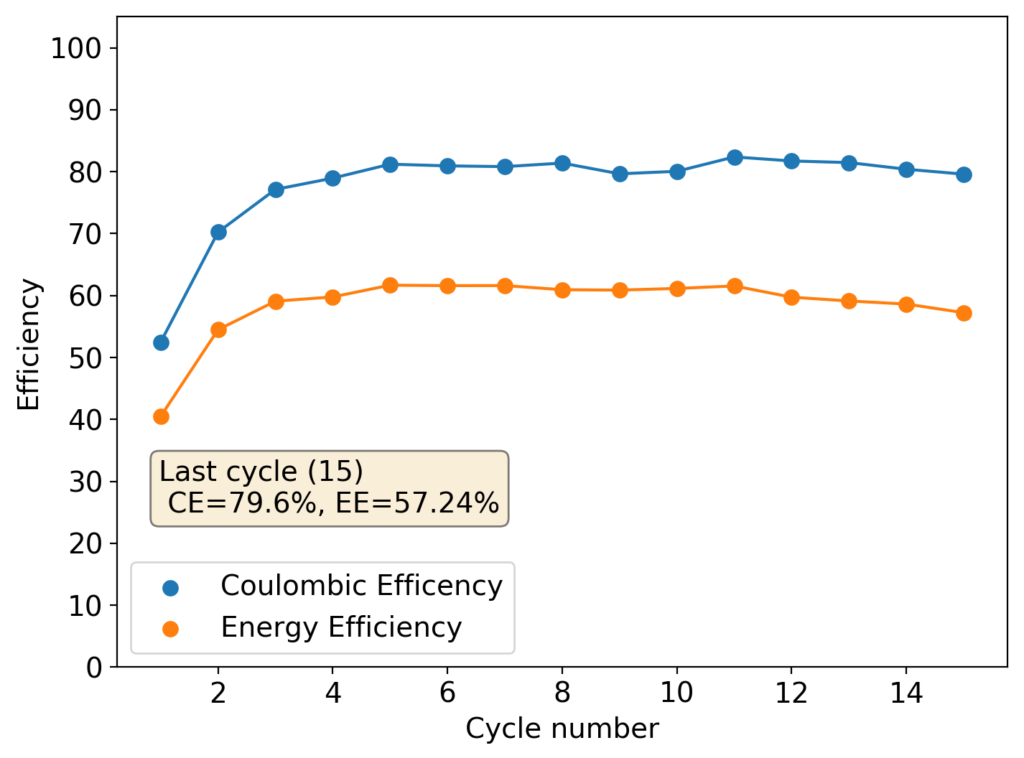
The results, shown below, illustrate the problem of trying to create a Zn-Br battery without a sequestering agent. The lack of a sequestering agent means that the formed bromine is easily able to exit the cathode material and go into the separator, migrating towards the anode. The cell’s behavior is similar to my batteries with sequestering agents, as during the first few cycles the cathode losses a lot of bromine to the media due to the lack of any oxidized bromine species in the separator and therefore starts at a lower Coulombic and Energy efficiency.
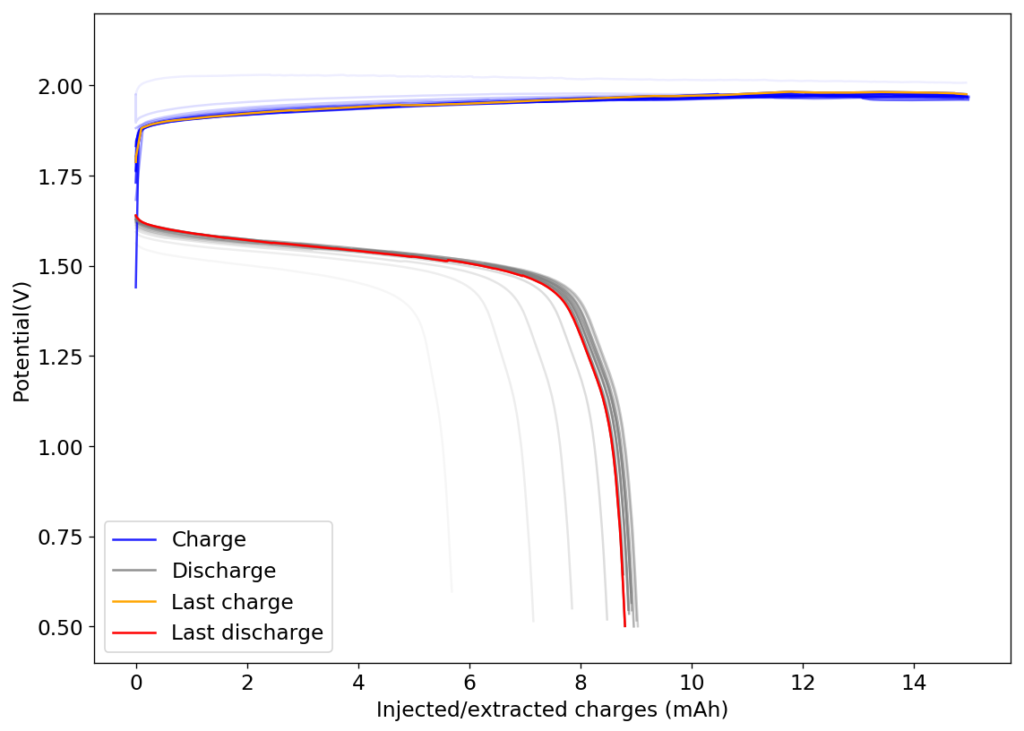
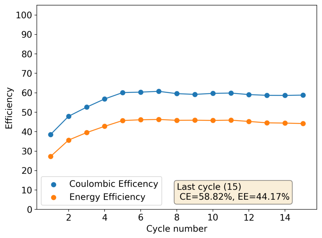
However, as the battery progresses, the Zn-Br battery assembled without a sequestering agent stabilizes at a CE of around 60% and an EE of around 45%, while with a sequestering agent, these values go up all the way to 90% and 65%. It is therefore evident that the sequestering agent does a good job of keeping the formed bromine in the cathode material, while the lack of a sequestering agent makes the battery significantly less efficient.
The energy density also changes quite dramatically, with the sequestering agent battery reaching around 25Wh/L and this design without one reaching only close to 17Wh/L. The use of a sequestering agent improves almost all aspects of the battery, except perhaps the stability of the battery which is lower if the sequestering agent reacts in any way with the electrodes or the bromine as a function of time.
I am going to continue cycling this battery in order to see if it reaches the same stability limits as my other devices or if it is able to run significantly longer. Batteries containing sequestering agents and charged to 15mAh have shown to deteriorate substantially at around 60-70 cycles, particularly batteries using TMPhABr as the sequestering agent. If these batteries without the sequestering agent are more stable then the stability issues of my designs using a sequestering agent could be assigned to chemical instabilities of this agent within the electrochemical environment.