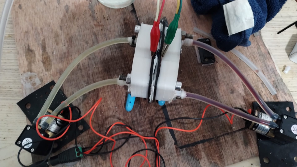
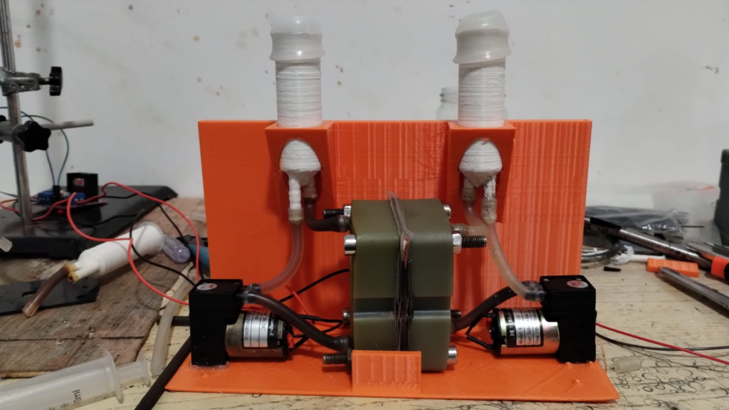
A recent Chinese Nature paper showed how Sodium sulfamate can be used in Zn-Br batteries to sequester active Br2 into an N-bromosulfamate that is much less aggressive, much more water soluble and even more easily electrochemically reversible than elemental bromine. I also wrote a recent post discussing the potential use of nicotinamide to achieve this (plot twist, it doesn’t work as the nicotinamide Zn complex is not very soluble). In today’s post I want to share with you my attempts at reproducing this chemistry of the Chinese paper using our open source flow battery dev kit.
The paper is very extensive and shares multiple formulations, they share a formulation for normal asymmetric cells as well as formulations to run the batteries using microporous Daramic membranes. Thankfully I have a bunch of 900um Daramic (thanks a lot to Daramic who donated these membranes to us for research). I bought some Sodium sulfamate (NaSA), Zinc bromide (ZnBr2), Potassium bromide (KBr) and potassium acetate (KAc) and proceeded to run some tests.
My tests using the formulations that they disclose exclusively for daramic were not very successful. Formulations using only ZnBr2, KAc and NaSA suffer from either lower capacities because of lower conductivity or issues with hydrogen evolution. This was specially the case when I tried the ZnBr2 1M, KAc 1.5M, NaSA1.5M formulation, which they suggest in the supporting information to reach >50Ah/L. However I think this is a typo and they meant 2M ZnBr2. If you read that paragraph in the supporting information closely you’ll realize why this is the case (they previously refer to a ZnBr2 1M solution and then say this is basically 2x that, but still write it as ZnBr2 1M).
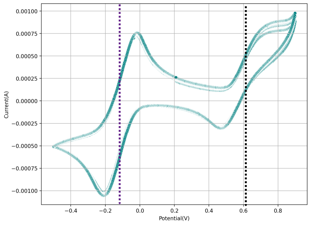
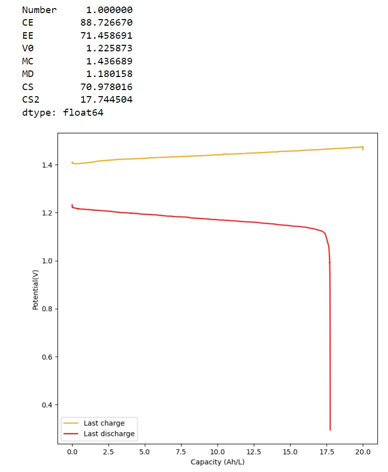
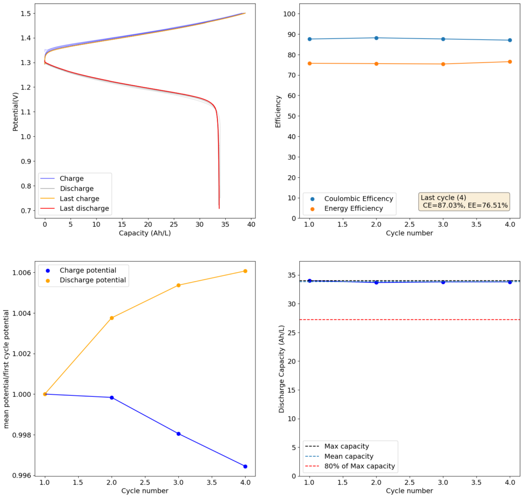
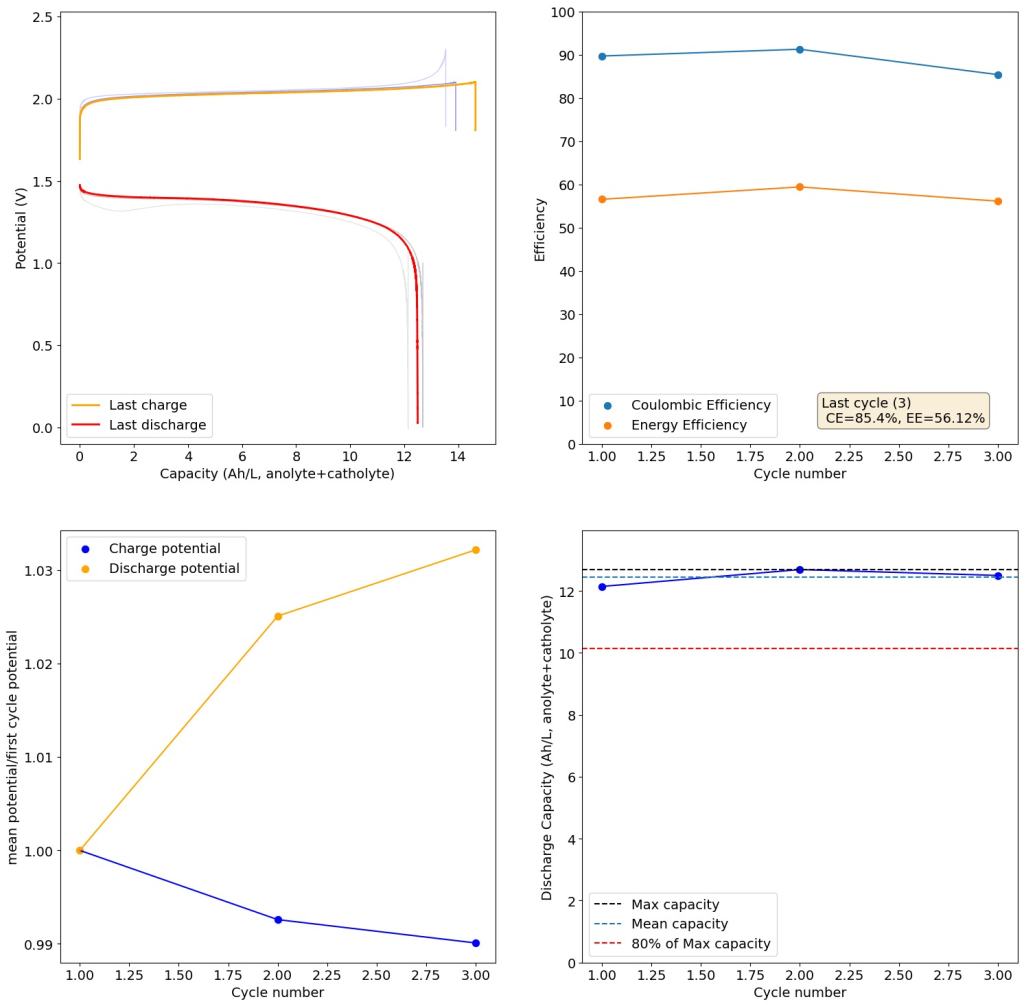
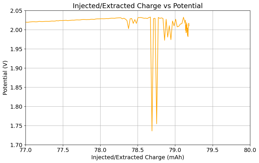
I then proceeded to test using some of the electrolytes they suggest for asymmetric cells, which were much more successful. In particular the 1M ZnBr2, 2M KAc, 1M KBr and 1M NaSA was great, with high CE values and decent EE values (see graph above). I didn’t experience dendrites before reaching the Nernst limit of the cells when using the 900um thick Daramic, which suggests plating is not as aggressively dendritic as with other electrolytes. However dendrites are quite evident when using 300um Daramic, suggesting you need around 300um of Daramic for every 30mAh/cm2. This might explain why the paper restricts most plating to below 90mAh/cm2 when using the 900um Daramic. I have yet to reproduce the Chinese group capacity or cycling stability values, but I believe I have validated the electrochemical principles well.
It is also worth noting that the Chinese group does some fancy functionalization of their felt with both nitrogen containing groups and carbon nanotubes, which aggressively boosts the conductivity and energy efficiency of the felt for the Br reactions. This is an important different that might justify why they get energy efficiencies closer to 75-80% while mine are just shy of 60%. I also haven’t optimized the compression ratio of my felt, which means that my felt might be under or over-compressed to extract the max EE in this setup. I also lack an oven to properly do air activation of the felt, so my felt is quite suboptimal and just used as-is.
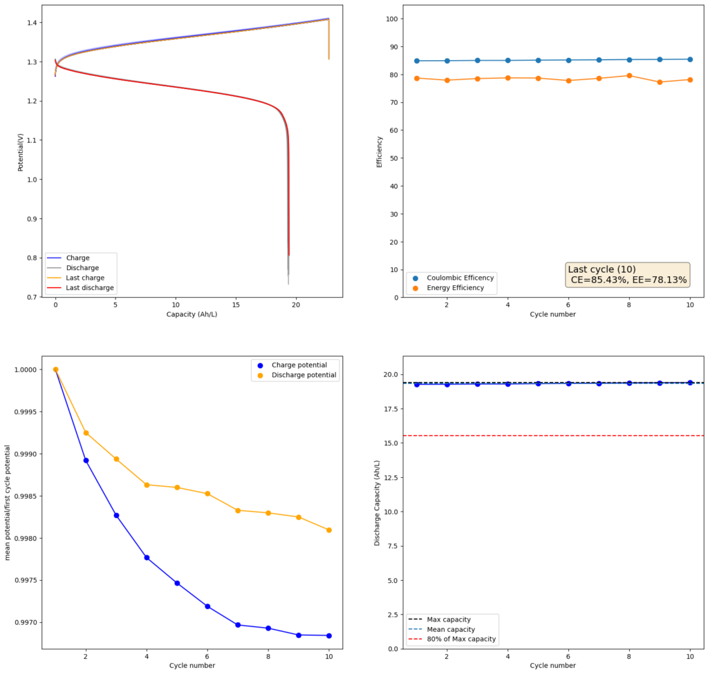
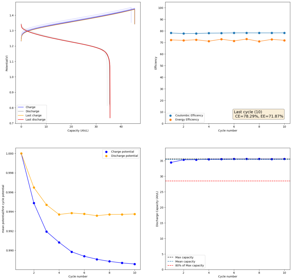
Furthermore, the paper successfully tested a true flow battery setup using Ti-Br. I cannot easily buy TiOSO4 but I decided to try to innovate and test this chemistry in a fully symmetric setup coupled with 0.5M of Fe-DTPA. While Fe-DTPA isn’t expected to be fully resistant to N-bromosulfamate, I figured it might last enough to provide me with some data. Given that the redox potential of the Fe-DTPA redox couple is quite lower than Fe2+/Fe3+, I figured it should give some appreciable voltage in an Fe-DTPA/N-Br-sulfamate battery. Fe-DTPA is also quite soluble and stable at the near neutral pH that favors the N-Br-sulfamate chemistry, so it should work nicely.
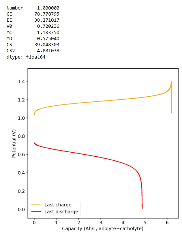
The results above, which have never been published before, show that this chemistry works to some extent. The low CE does suggest that a significant portion of the Fe-DTPA is somehow lost, perhaps to oxidation by atmospheric oxygen (I cannot purge my cells with N2 or Argon at the moment), but also likely from just interactions with N-Bromosulfamate across the microporous membrane. With that said, it does show that the new stabilized bromosulfamate chemistry opens up the window to some very interesting options that just didn’t exist before. Perhaps I can test nicotinamide in this setup, where there is no Zn to cause it to precipitate out of solution.
Finally, I wanted to dedicate the above post to Robert Murray-Smith, a fellow chemist in the UK who passed away recently and was a key inspiration for the start of this blog. I know his passing has been very sad for a lot of us in the DIY community, the curiosity and inspiration he instilled in a lot of us will live on. Thank you Robert!