On my last post I wrote about the potential of using Fe/Mn in acidic solution to create an Fe/Mn flow battery. I cited a paper published a few years ago which shows that you can achieve reversible Mn3+ chemistry in a solution of sulfuric acid and hydrochloric acid, I then proceeded to confirm this reversibility using cyclic voltammetry of Mn2+ solutions in hydrochloric acid.
However, it quickly became clear from analysis of the paper that this was only at very low capacities. This is because Mn3+ becomes unstable as its concentration increases in solutions, turning into MnO2 and Mn2+.
Given the very low volumetric densities that can be achieved with the acid setup, there’s no option but to revisit the use of more stable and reversible forms of manganese. The best candidate seems to be Mn-EDTA. This complex has already been shown to work in flow batteries at the 0.5M-1.0M range (see here).
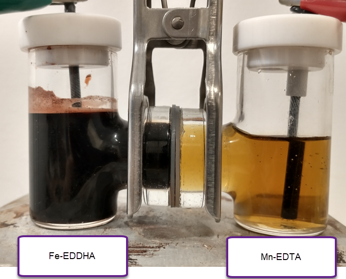
I had already thought about using this complex and wrote several posts about its potential use in combination with Fe-EDTA or Fe-EDDHA (see here). However, there is a big problem with the pH compatibility of the Mn-EDTA with the Fe-EDTA or Fe-EDDHA. The issue being that Mn3+-EDTA is only stable under acidic pH conditions, where the solubility of both Fe-EDTA and Fe-EDDHA is limited to around 0.1M. These chelates are only highly soluble under basic pH conditions, which are fully incompatible with Mn-EDTA.
The question is whether there is any easily accessible Fe chelate that is both compatible with Mn-EDTA in solution (so that we can create a symmetric electrolyte) and that can create soluble solutions at >0.5M concentrations in a pH ~5-6 buffer. Note that I need both chelates to be dissolved at >0.5M at the same time since I want the electrolyte to be symmetric so that it can work using a microporous membrane.
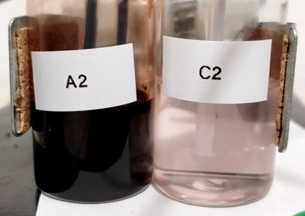
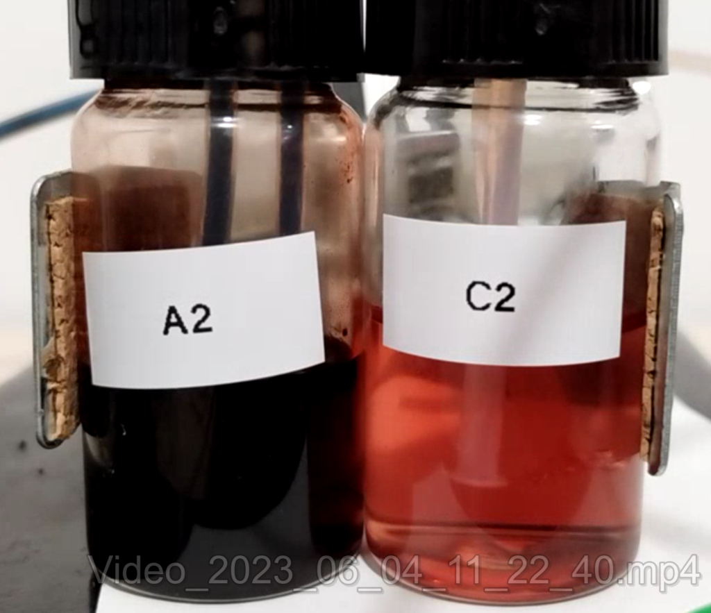
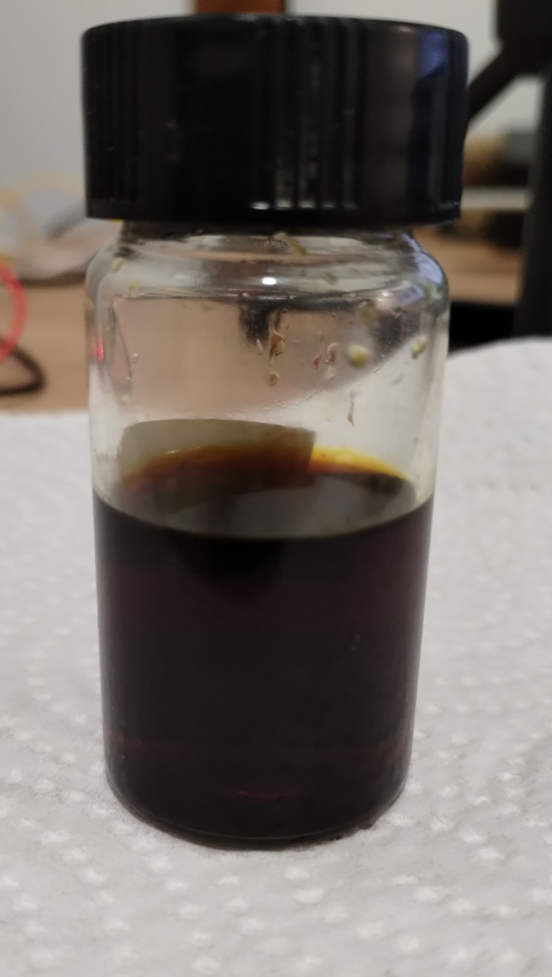
The answer is Fe-DTPA. This chelate is highly soluble at acidic pH values and – best of all – it is soluble enough to actually be in >0.5M solution in the presence of Mn-EDTA at this high concentration. Above you can see a picture of the Fe-DTPA+Mn-EDTA solution. The solution also contains an acetate buffer, which should ensure pH stability on charge/discharge, which should prevent degradation of the Mn-EDTA.
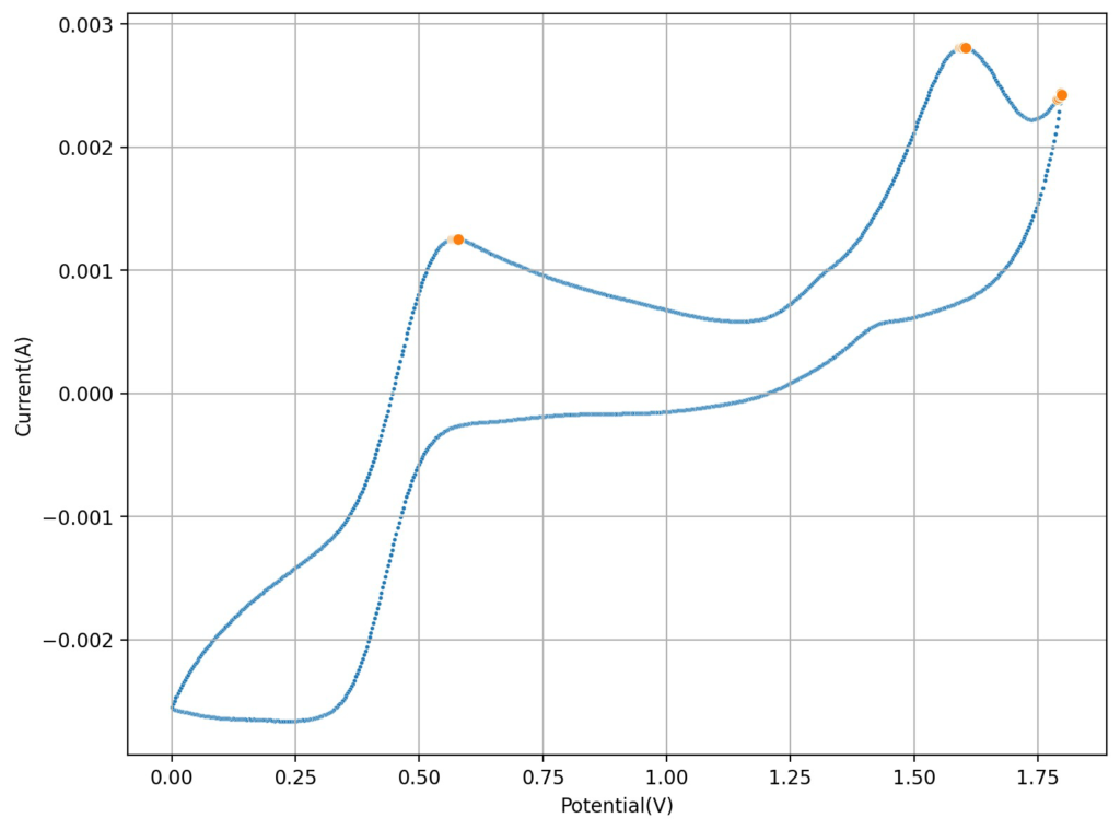
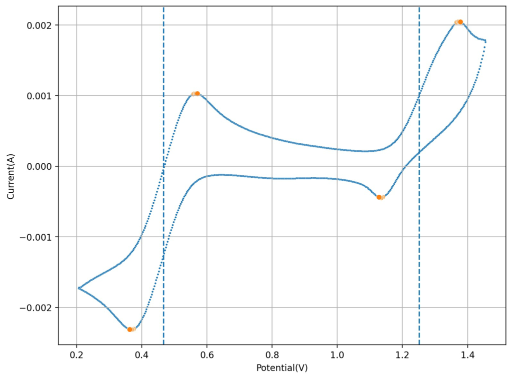
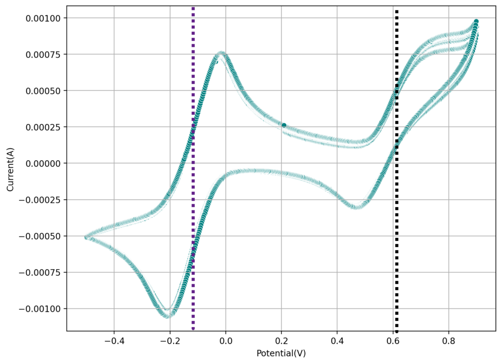
The second image shows a CV of the Fe-EDTA/Mn-EDTA buffered solution, showing that both the Fe and Mn electrochemical reactions are reversible. The half wave potentials are -0.11V and 0.61V, giving us an expected potential for the flow battery of +720mV. This is close to what I had measured before for Fe-EDTA/Mn-EDTA. This proves that the DTPA does not change the electrochemical characteristics of the system very much. The above test also confirms there acetate buffer is stable to the generated Mn3+-EDTA.
The next step is to build a flow battery using the above solution and see what performance characteristics we can get. With the current solutions this system will be limited to around 8-9Wh/L. However I haven’t tested the solubility limits of the chelates in this buffer.