On my last post, I showed the results of charging/discharging a flow battery using a ZnCl2+NH4Cl+KI electrolyte using 4 layers of Daramic as a membrane. However, while Daramic is a low cost material, it is not easily accessible for DIY testing at this moment. For this reason, I wanted to run some tests on materials that are easier to source than Daramic.
I looked for materials around my house that had similar porosity (0.1-5um). I tested several different papers that I had around but none of them worked very well. The porosity of most traditional printer papers is high, with most having 10-20um pore sizes. This means that you need many layers to prevent fast self-discharge from migration of the triiodide across the membrane. Additionally, the papers lost structural integrity quite easily.
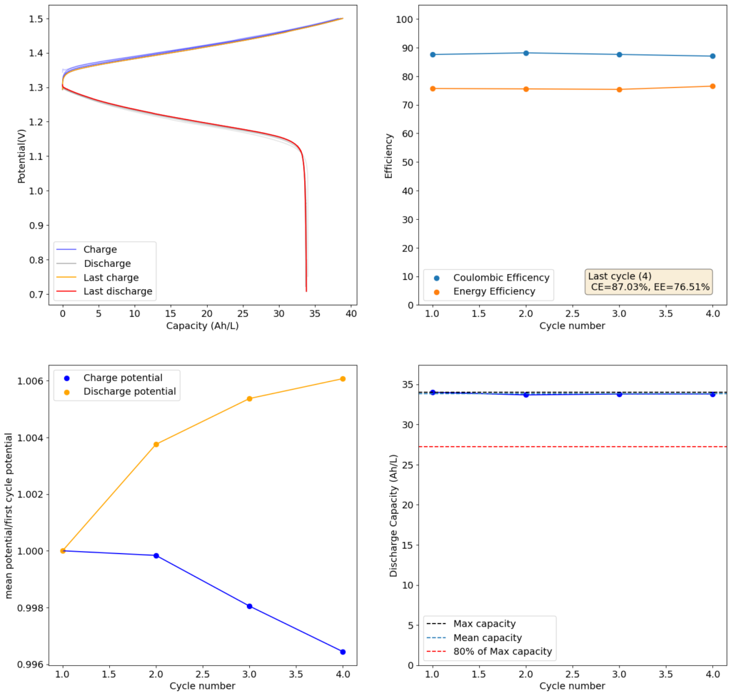
Test using a 2m ZnCl2 + 2m NH4Cl + 4m KI electrolyte at a current density of 20mA/cm2. Four layers of matte photo paper were used as separator.
Finally, I stumbled upon matte photo paper as a potential solution. This paper has much lower porosity with <5um pore sizes. Some of these papers might even have pore sizes that are below 1um. This is important for printing photographs, as low pore sizes implies that there is less bleeding of ink when it is applied to the paper, although ink needs to be applied much more slowly to the material (reason why printing with these papers is really slow).
For my initial test, I used 4 layers of matte photo paper. The paper does have a substantially higher ohmic resistance compared to Daramic, so I had to lower the current density to 20mA/cm2. I did 4 cycles of charge/discharge that you can see above (I only did 4 because the lower current meant cycling was quite slow). The CE of 87.54% and EE of 75.72% with a capacity of 33.8 Ah/L shows that photo paper is definitely a good choice for at least the short term cycling of these devices.
On inspection, the photo paper did not show any evident degradation although dendrite penetration happened just as much as it did with the Daramic separator. The separator was also completely black, fully permeated by the catholyte solution which contains triiodide in solution when charged.
After concluding my work with the Fe-Mn system, I still wanted to find a system that I could use to build flow batteries. With my new flow battery systems – which I got thanks to my colleague Kirk – I have been able to test different chemistries to come up with the most practical approach for an actual DIY flow battery.
To build such a battery, I first started with a list of requirements:
Easy to find chemical supplies.
Voltage at least equal to vanadium flow batteries (>1.2V).
Energy at least equal to vanadium flow batteries (>25Wh/L).
Efficiencies at least equal to vanadium flow batteries (>70% EE).
Mildly acidic or basic (no strong acids or bases).
Ideally uses a microporous membrane (no need for ion exchange membranes).
Long term cycling stability (>1000 charge/discharge cycles).
There aren’t a lot of systems that can comply with all the above requirements. One of the few that seemed plausible was the Zn-I system. In this system, Zn2+ is reduced to Zn metal on the anode and I- is oxidized to I2 (which quickly gets converted to I3–) in the cathode. The Zn can be plated with a good density, often at more than 100mAh/cm2 of cathode when using carbon felts.
Results of a 1m ZnBr2 + 1m KCl + 2m KI flow battery using 4 layers of Daramic as the microporous separator, carbon felt anode and cathode with a copper sheet as the anode current collector and a graphite plate as the cathode current collector. The current was 40 mA/cm2
Both the Zn/Zn2+ and I–/I3– couples are kinetically very fast – allowing for large currently densities – and have large energy densities. In particular, the solubility of their salts is quite large, so achieving solutions with concentrations >6M is not a problem. At 6M, the theoretical capacity of the battery is around 156Ah/L, rivaling even LiFePO4 batteries.
There are two main problems with this system. The first is the formation of Zn dendrites in the anode, which shorts the battery, and the second, the formation of solid I2 in the cathode after a state of charge of around 66%, which interrupts flow through the battery and causes it to fail. This means that the max State Of Charge (SOC), is often limited to 66% even if no dendrites are present (which is a big if).
Luckily some publications already exist showing that we can sacrifice some efficiency to overcome some of these issues. For example, this paper uses a polyolefin microporous membrane to obtain flow batteries that work at very high current densities and which can “cure” from overcharging due to the constant “leak” of iodine into the anode side. Since the same electrolyte is used as catholyte and anolyte, there is no problem with changes in composition as a function of time.
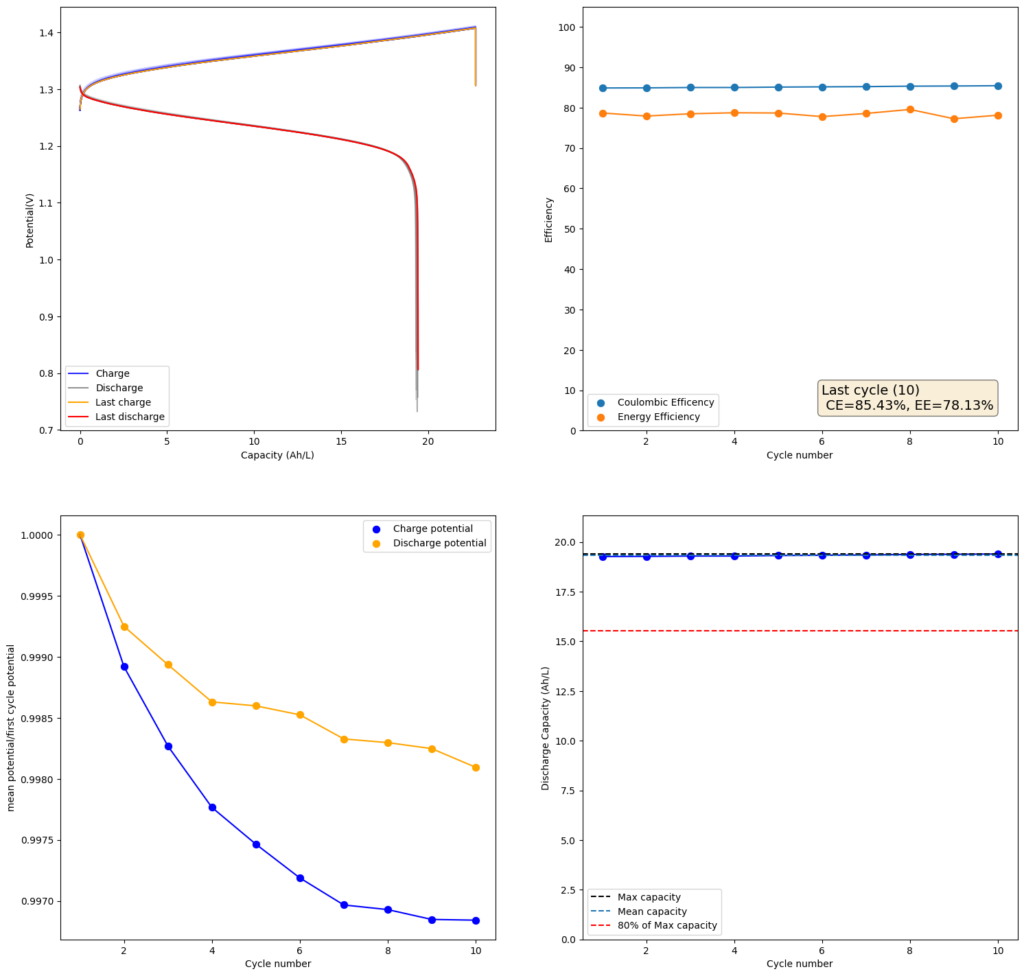
I decided to use this paper as a template and try reproducing their results. I started by making a 2m solution (this is moles of solute per kg of solvent). You can see my results in the first image above. I was able to obtain a charge of 19.3Ah/L since the 2m solution comes out to approximately 1.5M (because the final volume is larger), this comes out to an SOC of 48%. Trying to charge the battery higher ends up generating I2 solid in my cathode and therefore killing the battery (as no flow becomes possible).
My current was also lower (40mA/cm2 vs 80mA/cm2) because my potentiostat overheated at higher densities (which means I need to build some heatsink to test these current levels). Note that I also ran at higher mL/cm2 since my closed loop is exactly 1mL/cm2 while the paper runs at half of this, meaning that their Zn accumulation per electrode area is half. I also used 4 layers of Daramic to match the thickness of their polyolefin membrane (around 900um).
Results of a 1m ZnCl2 + 1m NH4Cl + 2m KI flow battery using 4 layers of Daramic as the microporous separator, carbon felt anode and cathode with a copper sheet as the anode current collector and a graphite plate as the cathode current collector. The current was 40 mA/cm2
The CE and EE values are pretty decent, but loses from crossover of the microporous membrane are evident. These loses have an advantage though as iodine that permeates the membrane dissolves any Zinc dendrites that might be perforating it, so the battery cycling is very stable.
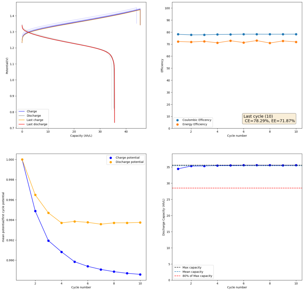
Since I didn’t observe any gain in SOC due to the presence of the Bromide, I tried to reproduce the results using a lower cost mixture of ZnCl2+NH4Cl+KI. This time I also increased the concentration to 4m to see if I would get a proportional gain in the capacity. The results of this test are showed in the second image in this post.
As expected, there is a drop in the CE and the EE of the device (as more crossover can happen at longer charging times) but the capacity of the battery increases proportionately as well. I was able to charge to double the amount, but the discharge capacity did not increase as much, due to the drop in efficiency. This time I was able to get 35.5Ah/L out of the battery, which is an SOC of around 42%. This is however, already higher than a Vanadium flow battery normally offers (~25Ah/L). Note that higher concentrations are not possible in my system with 4 layers of Daramic as dendrites will start fully crossing the separator at a density of around 56mAh/cm2 (while charge density in the last test is 45.45mAh/cm2).
As you can see, the Zn-I system with a microporous membrane is great. It is stable, has decent energy density, supports large currents and does not require an expensive ion exchange membrane. There are certainly potential improvements to increase the available SOC, but even at the current levels, the system would already be useful in practical applications. Higher separator thickness could also increase the CE and EE of the battery system, without much compromise to the ohmic resistance. Small modifications to the separator – such as adding a carbon coating – can also increase its selectivity and reduce the extent of Iodine migration. Note that you do not want to completely stop it as stopping it leads to dendrites shorting the battery.
I also tested some other microporous membranes that could be easier to obtain than Daramic. Interestingly enough, photographic paper – which has a pore size similar to Daramic – works just as well in this system (really cheap as far as membranes go). I will share the results of these tests in a future post.