Monthly Archives: October 2020

Zinc Bromine Batteries: PEG-200, bubbles and over-potential

In my latest separator-free cells that use a PTFE o-ring spacer, I am now testing some additives to reduce dendrites and increase the life of the cells. A popular additive – PEG-200 – has proved not to be viable at a concentration of 20% due to large losses in the cell’s voltaic efficiency, moreover PEG-200 at a concentration of 1% offers little protection against dendrite formation. This last experiment tried a PEG-200 concentration of 6%, coupled with a small amount of NaCl to attempt to increase the conductivity and compensate for the loss caused by PEG-200.

Charge to 25mAh at 15mA, discharging to 0.5V. Electrolyte contains 0.1M NaCl, 3.0M ZnBr2, 6% PEG-200

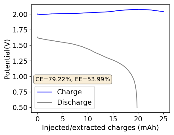
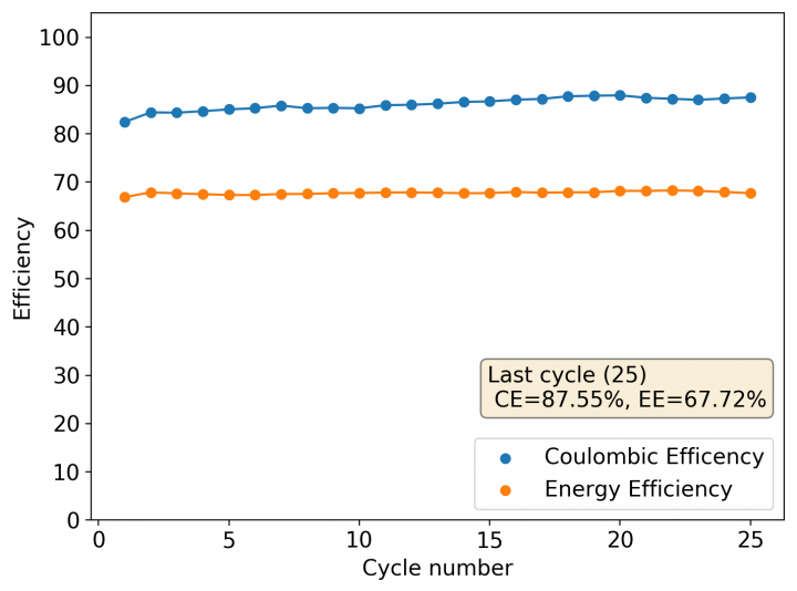
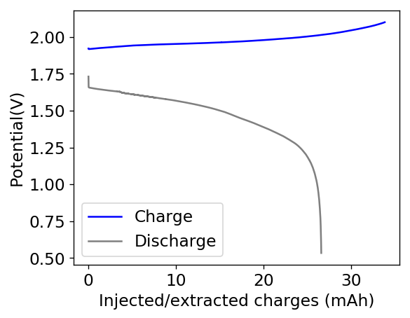
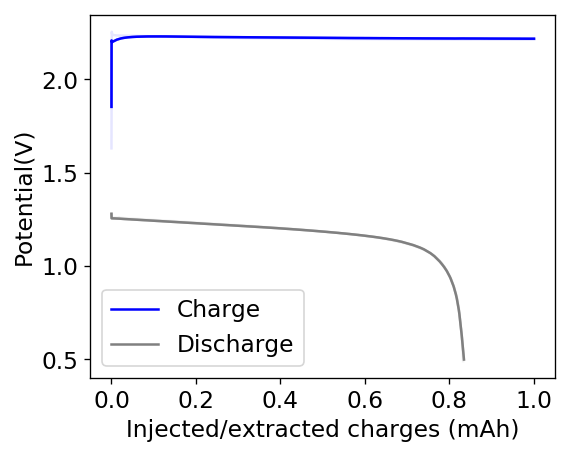
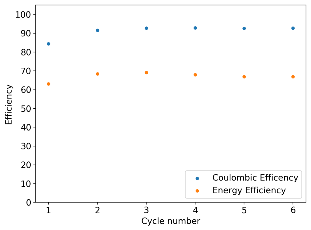
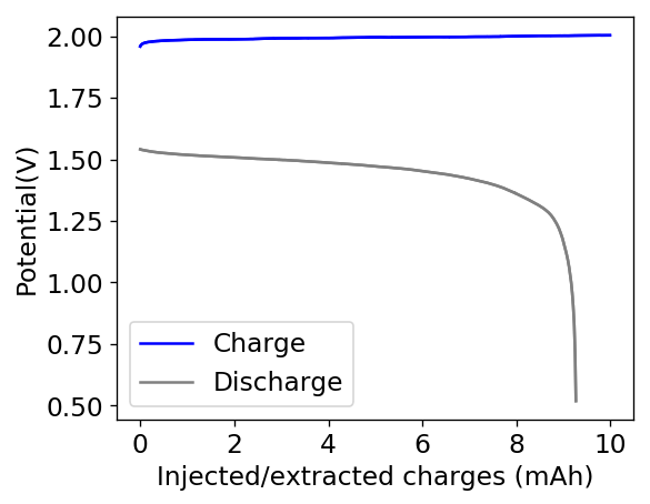
Above you can see the charge/discharge curve measured for this device. Compared to my previous devices the Coulombic and energy efficiencies have dropped significantly, with the most dramatic drop being in the energy efficiency. This value has dropped more than 10% relative with previous devices using a 1% PEG-200 concentration at the same zinc bromide concentration.

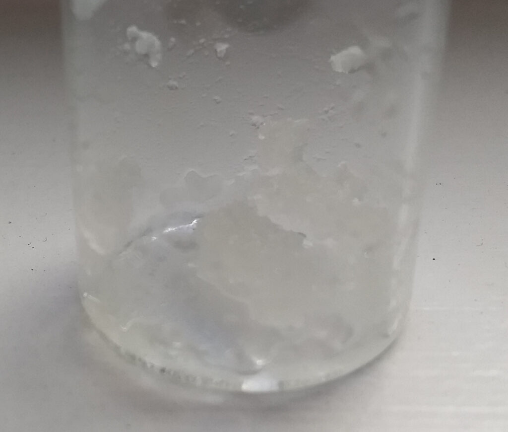
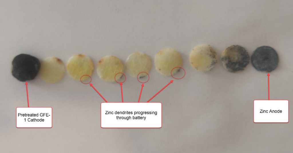
A device with this energy efficiency will not be viable, so I saw no need to cycle the battery multiple times. However to answer the question of whether zinc dendrites are formed or not, I then charged the cell a second time to 25mAh and opened the device, taking the picture of the anode shown below (I apologize if it seems out of focus, it wasn’t very easy for me to focus on such a small amount of space with my camera).

Graphite anode after one charge/discharge cycle and a subsequent charge cycle to 25mAh.

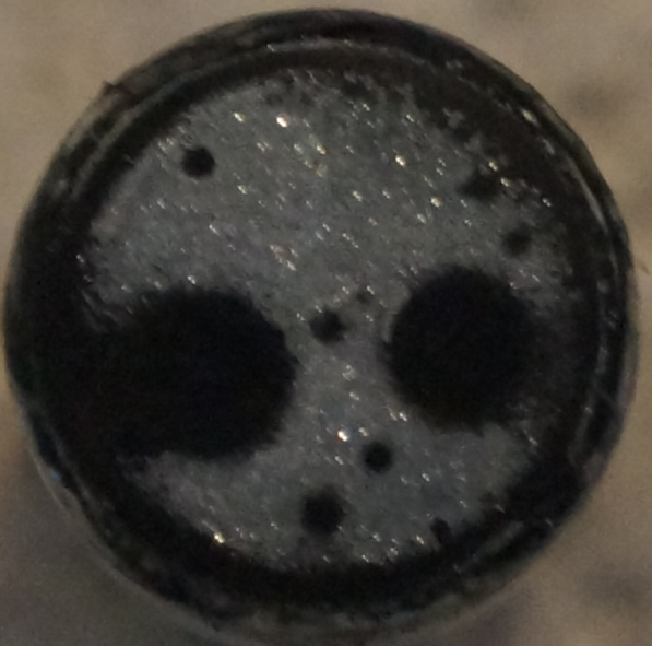
The picture above shows some interesting results. First, it was evident that there was absolutely no zinc dendrite formation, the plating was very crystalline and the electrode was flat with no protruding dendrites. Previous cells that had dendrite related failures show very tall dendrites that can easily be seen with the naked eye, even after only a few cycles. However you can also see several big and medium holes in the electrode where absolutely no zinc was deposited, this was caused by “air bubbles” trapped when the Swagelok cell is closed, which I haven’t been able to find a method to consistently remove. These bubbles remove so much of the surface area of the electrode that they can be responsible for significant losses in voltaic efficiency. Pre-wetting the electrode seems to be a viable method to ameliorate the issue but isn’t perfect.

In order to see if a cell like this can be viable, I am now testing a 6% PEG-200, 3M ZnBr2, 1.7M NaCl electrolyte, which should dramatically reduce the voltaic losses caused by the PEG-200 by increasing the conductivity of the electrolyte. Stay tuned for these results.

Zinc Bromine Battery: Teflon o-ring separators, capacity and PEG-200

In my previous post, I described my first tests of separator-less batteries using a PVC spacer. This turned out not to be a very good idea, due to the reactivity of PVC with bromine. Although the battery was able to run for 20+ cycles successfully, a lot of noise started to happen within the measurements. After opening up the battery, it was evident that the separator had degraded (it turned from black, to a whitish gray color). Due to this reactivity I decided to change my plans to work with Teflon o-rings as spacers (which I bought here). These are of the exact diameter I needed. Given the height of the spacers, I decided to use 3 (total height of 5.2mm) in order to match the same height of the previous cells I was building using fiberglass separators. This gives a total battery volume of around 0.68mL, counting the volume of the separators.

Battery built using PTFE spacers, GFE-1 cathode pretreated with 10% TMPhABr + 3M ZnBr2 + 1% PEG-200. Charged to 15mAh at 15mA, discharged to 0.5V.

The results for the first battery tested using this configuration is shown above. The energy density of this battery is around 30Wh/L and I was able to cycle it at this current density and charge capacity for 25 cycles without running into any problems or instabilities. At this point I decided to test what the maximum capacity of the battery could be, by charging the battery until the potential reached 2.1V.

With this test I was able to charge the battery to a capacity of around 60Wh/L, but this capacity usage is not sustainable given that the battery completely died on the next cycle due to the formation of a large amount of Zinc dendrites. This means that the usable capacity under this amount of 3M ZnBr2 electrolyte is likely to be around 75% of this value – given what we know from published research and patents – which should be at least 25mAh.

Maximum capacity test charging the battery until potential reached 2.1V at 15mA. We were able to recover 26.56 mAh discharging to 0.5V.
Charge/discharge curves of a battery with the same configuration charging to 25mAh at 15mA, discharging to 0.5V. Notice the instabilities on discharge.
Evolution of efficiency variables as a function of the cycle for the battery shown on the previous image.

After building another battery and charging to 25mAh – taking the energy density to ~45 Wh/L – there were substantial instability issues appearing on the discharge curves after 7 cycles. I believe these instabilities are due to Zn dendrites that fall from the anode into the cathode, temporarily killing the discharge potential of the device until the Zn dendrite is dissolved. These instabilities are correlated with loses in both the Coulombic and energy efficiency values of the battery, deteriorating the performance as a function of time.

Due to the above issues, it seems important to try to reduce dendrites to prevent problems at these capacities. I decided to try a PEG-200 additions at 20% to see what would happen. With this configuration, a 20% PEG-200 addition generated too much voltaic loses because of the huge increase in internal resistance. Even when charging/discharging to only 1mAh, the necessary potential was already above 2.15V, with the energy efficiency dropping below the 35% mark. You can see one such cycle in the image below.

Battery built with a 20% PEG-200, 3M ZnBr2 electrolyte. Otherwise identical to other batteries shown in this post.

Because of the above results, it is clear that a PEG-200 addition is likely going to need to be below the 10% mark in order to be viable. I have since prepared an electrolyte comprised of 3M ZnBr2, 6% PEG-200 and 0.1M NaCl in order to see what the behavior is when trying to charge to these higher capacity values. Up until now charge potentials at 15mA are higher than for the 1% PEG-200 cells, but low enough (2-2.1V) to prevent heavy voltaic loses. We’ll see what sort of efficiencies and Zinc deposits we can get with this electrolyte configuration.

Zinc Bromine Batteries: Making higher purity zinc bromide from readily available salts

Although Zinc Bromide is a readily available commodity chemical in some parts of the world (readily available in bulk quantities or for businesses), it is difficult to source in places like the US due to a lack of retail applications to justify its sale to the general public. Small amounts can be bought from sources on ebay/amazon, but the cost can often be above 1 USD/gram with similar costs from Alibaba when buying small quantities (<10kg). For people wanting to do small/medium scale experimentation on Zn-Br batteries, it is often impractical to buy in the necessary quantities, so a low cost synthesis of Zinc Bromide from readily available chemicals is desirable.

Crude Zinc Bromide produced through the process described in this article before being put into the desiccator.

The cheapest solution I have found comes from the use of readily available Zinc Sulfate and Sodium Bromide. Both of these salts are available in high purity at very low retail prices (<10 USD/kg even when buying sub kilogram quantities). Since Sodium Sulfate is significantly less soluble than Zinc Bromide, preparing a very concentrated solution containing both salts leads to the precipitation of Sodium Sulfate with Zinc Bromide remaining in solution. The problem with this approach is that the solution always contains a substantial amount of Sodium Sulfate and the many separation/concentration/crystallization steps involved to obtain higher purity ZnBr2 make it a rather impractical approach if higher purity Zinc Bromide is required or if you want to achieve the result quickly.

My solution to this problem is to use a readily available organic solvent – rubbing alcohol – to help speed up the process and achieve better results. Here’s a summary of the synthesis for a small amount:

  1. In a 50mL tall beaker add ~20mL of distilled water and dissolve 5.5g of Zinc Sulfate Monohydrate and 6.1g of Sodium Bromide. Note that an excess of the Zinc Sulfate is used, as it is the least soluble of the reagents.
  2. Stir the mix until everything is fully dissolved. All the formed salts should be soluble enough to dissolve in this amount of water at 25C (77F)
  3. To this solution, add ~20mL of rubbing alcohol.
  4. Stir the mix for a couple of minutes.
  5. Let the solution set until everything separates. Three distinct layers should form (one solid, two liquid). The Sodium Sulfate will precipitate and a bottom aqueous layer will form while a top alcohol layer will remain.
  6. Decant the top alcohol layer and collect it. This layer contains no salts and can be used for future batches.
  7. Transfer the bottom aqueous phase to another container. The solid precipitate is normally well formed enough as to allow for transferring the bottom aqueous layer to another container without the need for filtering. The remaining solid is sodium sulfate plus the excess zinc sulfate.
  8. The aqueous layer transferred contains all the Zinc Bromide. You can heat and evaporate most of the water, but bear in mind that the Zinc Bromide will hold very tightly to it and might start to sizzle and “erupt” aggressively as you heat more and more (it’s similar to when water splashes into hot oil). Since the aqueous layer contains some alcohol make sure you do this in an open or very well ventilated space. It is better to reduce the volume until the point where the ZnBr2 starts to crystallize and then transfer it to a desiccator so that it can finish its drying process. A container with anhydrous Calcium Chloride or anhydrous Magnesium Sulfate can do the job.

The above described process – using rubbing alcohol – has the advantage of producing the Zinc Bromide quickly, without the need to perform successive steps of cooling/decanting/filtering/crystallizing, etc. Since both Sodium Sulfate and Zinc Sulfate are almost completely insoluble in alcohol containing solutions – while Zinc Bromide is not – this leads to a significantly faster and more satisfactory synthesis from readily available chemicals. Using a slight excess of zinc sulfate is recommended to avoid the presence of Sodium Bromide in the final solution.

The only tricky part is taking the Zinc Bromide out of the final solution. I prefer not to heat it till it’s completely dry, since the sizzling and “eruptions” of the Zinc Bromide can be pretty aggressive as it tries to hold dearly to every milligram of water it can manage to. Besides, if you heat it to dryness it will quickly become wet again as it cools unless you immediately put it inside a desiccator. It is therefore preferable to put this in a desiccator as soon as Zinc Bromide crystals start to appear and let the drying agent get all the water out of the Zinc Bromide. Note that a desiccator doesn’t need to be anything fancy, some air-tight tupperware you fill with a good enough drying agent can do (the drying agent needs to be more hygroscopic than Zinc Bromide).

I haven’t scaled this process up – as I only work at very small scales – so I don’t know what problems could occur at larger scales. Since it involves alcohol I would advice working at a small scale to see if this process might fit your needs and to be careful and follow all safety precautions.

Zinc Bromine Batteries: Trying a configuration without a solid separator

During my quest to build and characterize a zinc-bromine battery, I have mainly focused on the use of non-woven fiberglass separators between carbon electrodes in order to hold the electrolyte in the device. This is because some of the research papers with the most promising results for these batteries use this type of separator. Having a solid separator makes the battery easier to construct and easily translates to the construction of both coin-cell and pouch devices, which are the two classic prototype devices used in the modern battery industry. Moreover, a solid separator substantially increases the mechanical stability of the cell and reduced the influence of gravity on the device, making it less susceptible to changes in orientation. The image below details the best structure I have achieved so far for this type of device.

Most successful structure so far for the batteries I have built in my Swagelok cell. Note the cell was never measured in any preferred orientation, the cell was placed horizontally for measuring.

However, one big problem of having a solid separator has been the existence of edge effects at the border of the separator. Batteries have grown Zinc dendrites around the edges of the fiberglass separator, despite my best efforts to attempt to avoid them. While using a 20% PEG-200 concentration and increasing the concentration of Zinc Bromide to 3M helped to largely eliminate dendrite formation, none of these or other modifications were able to fully prevent the problem.

Dendrites formed within a solid separator are quite problematic, because they cannot be fixed and lead to extremely limited battery lifetime. Even if the battery is fully shorted to try to eliminate these dendrites, the mechanical damage to the separator caused by the dendrite structure is permanent, unless more expensive self-healing separators are used. Furthermore, a dendrite can partially react with perbromide coming from the cathode and be cut “half-way” effectively leaving some Zinc stranded in the middle of the battery which is only going to be slowly removed by reactions with diffusing bromine or perbromides.

New battery cell structure I am trying. Note that the batteries are going to be tested in this exact orientation, as the lack of a solid separator means that bromine will accumulate in the bottom electrode, so this electrode has to be the cathode.

For the reasons highlighted above, I have decided to try separator-less batteries in order to see if these batteries can effectively avoid the dendrite problem while still retaining or improving on the coulombic and energy efficiency values I have achieved so far. To do this I have used a 2mm piece of PVC shrink tubing as a separator, cutting it so that it forms a 2mm x 35mm strip that can go around the internal diameter of my Swagelok cell (0.5 inch diameter) and prevent the upper electrode from contacting the bottom electrode. The space is then filled with electrolyte and the cell is closed, with the spacer preventing any additional compression of the cell.

The biggest advantage of this configuration is that it can be easily maintained, since the cell can be opened and the electrodes can be easily changed or cleaned. The lack of a solid spacer also means that any Zinc dendrites that form will either dissolve as they touch the lower electrode or fall and just discharge the battery, while they will never be “stranded” in the middle of the battery. Large amounts of dendrites might still lead to battery shorts, but given that I am using 20% PEG-200 and there are no longer any separator related edge effects, I hope this will stop being a huge problem.

Coulombic and energy efficiency as a function of the charge/discharge cycle for first battery under the above configuration
Charge/discharge curve for last cycle in the previous image. Charge/discharge is done at 10mA.

The first prototype battery put together in this configuration – 3M ZnBr2 + 20% PEG-200 solution – has been able to survive 6 charge/discharge cycles, charging to 10mAh and discharging to 0.5V, both at 10mA. The battery has an energy density of 21.6 Wh/L, given its current geometry (all battery components) but I am hopeful this energy density can be pushed closer to 40 Wh/L after I confirm that dendrite formation is not an issue under this electrolyte conditions. Previous batteries in a fiberglass separator were able to sustain 10-20 cycles under these conditions before showing important shorting issues due to dendrite formation, so we will see how far this prototype battery can go before disaster strikes.

Zinc Bromine: Pushing energy density beyond 40 Wh/L

For Zinc-Bromine batteries, energy density is a key characteristic since these batteries are bound to be used under circumstances where the specific energy (Wh/kg) is not as relevant as the amount of space taken by the batteries to store a given amount of energy (like utility level energy storage). Given this fact, I wanted to explore how hard I could push the capacity of a Zn-Br battery to try to maximize its energy density.

I built a cell with a GFE-1 cathode pretreated with a 50% TMPhABr solution, used 16 layers of fiberglass separator (total cell height 0.53cm, total area 1.29cm2, volume 0.68mL), used a 3M ZnBr2 + 20% PEG-200 solution to minimize dendrites as much as a I could. I then tried to charge the cell to 30mAh, see what sort of efficiencies I could get. I used a current of 5mA since the 20% PEG content and highly loaded GFE-1 cathode both substantially increased the internal resistance of the device.

The battery was charged to 30mAh, then discharged to 0.5V, both charge and discharge were performed at 5mA. CE=81.08%, EE=62.35%.

Given the results shown above, I was able to achieve an effective stored charge of 18.7mAh, which gives the cell an energy density of 43.76 Wh/L. This puts the battery above the values that are achieved for commercial Zinc-Bromine flow batteries (5.7–39 W·h/L). However not everything was as good as I thought, as the battery shorted during the second cycle due to the formation of Zinc dendrites. I was however very puzzled by the presence of Zinc dendrites at a 20% PEG-200 concentration, so I decided to open up the battery and peel the layers to see what was going on.

As you can see in the image below, zinc dendrites form predominantly across the first 3 layers of fiberglass separator, which means that the PEG-200 was indeed effective at preventing dendrite formation from advancing too much through the battery (without PEG-200 you would see a significant presence of dendrites all the way to the cathode). However there were some Zinc dendrites forming predominantly close to the edge of the battery and these progressed all the way to the cathode material, although it is very hard to see their presence without magnification within the last couple of layers.

Layers of Zinc-Bromine battery after the battery was shorted by Zinc dendrites.

The fact that I am using a Zinc anode that is cut from a 0.2mm sheet with a perforator might have something to do with it, as the Zinc is bound to be extremely sharp at the edges – therefore high surface area – due to the cutting process. This is the perfect spot for the formation of dendrites and – due to the smaller amount of electrolyte at these points – could easily lead to the formation of dendrites moving through the battery, which is what we have observed. This also happened at a point where the Zn anode was particularly sharply cut, which further reinforces this hypothesis.

In order to see if the Zinc anode and the way it’s cut has a lot to do with this fact I have decided to repeat the above experiment using the graphite electrode as anode – without the presence of any Zinc anode – which should show if zinc dendrites are able to form all the way to the cathode in the presence of large concentrations of PEG-200. If Zinc dendrites do not form in this case, I will move to the use of graphite for the anode material from now on.