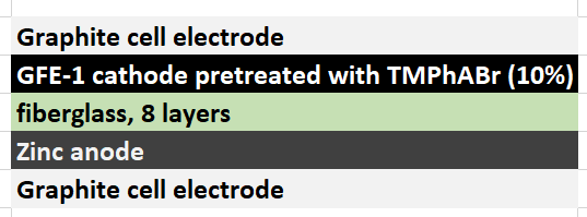
During my quest to build and characterize a zinc-bromine battery, I have mainly focused on the use of non-woven fiberglass separators between carbon electrodes in order to hold the electrolyte in the device. This is because some of the research papers with the most promising results for these batteries use this type of separator. Having a solid separator makes the battery easier to construct and easily translates to the construction of both coin-cell and pouch devices, which are the two classic prototype devices used in the modern battery industry. Moreover, a solid separator substantially increases the mechanical stability of the cell and reduced the influence of gravity on the device, making it less susceptible to changes in orientation. The image below details the best structure I have achieved so far for this type of device.
However, one big problem of having a solid separator has been the existence of edge effects at the border of the separator. Batteries have grown Zinc dendrites around the edges of the fiberglass separator, despite my best efforts to attempt to avoid them. While using a 20% PEG-200 concentration and increasing the concentration of Zinc Bromide to 3M helped to largely eliminate dendrite formation, none of these or other modifications were able to fully prevent the problem.
Dendrites formed within a solid separator are quite problematic, because they cannot be fixed and lead to extremely limited battery lifetime. Even if the battery is fully shorted to try to eliminate these dendrites, the mechanical damage to the separator caused by the dendrite structure is permanent, unless more expensive self-healing separators are used. Furthermore, a dendrite can partially react with perbromide coming from the cathode and be cut “half-way” effectively leaving some Zinc stranded in the middle of the battery which is only going to be slowly removed by reactions with diffusing bromine or perbromides.
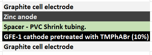
For the reasons highlighted above, I have decided to try separator-less batteries in order to see if these batteries can effectively avoid the dendrite problem while still retaining or improving on the coulombic and energy efficiency values I have achieved so far. To do this I have used a 2mm piece of PVC shrink tubing as a separator, cutting it so that it forms a 2mm x 35mm strip that can go around the internal diameter of my Swagelok cell (0.5 inch diameter) and prevent the upper electrode from contacting the bottom electrode. The space is then filled with electrolyte and the cell is closed, with the spacer preventing any additional compression of the cell.
The biggest advantage of this configuration is that it can be easily maintained, since the cell can be opened and the electrodes can be easily changed or cleaned. The lack of a solid spacer also means that any Zinc dendrites that form will either dissolve as they touch the lower electrode or fall and just discharge the battery, while they will never be “stranded” in the middle of the battery. Large amounts of dendrites might still lead to battery shorts, but given that I am using 20% PEG-200 and there are no longer any separator related edge effects, I hope this will stop being a huge problem.
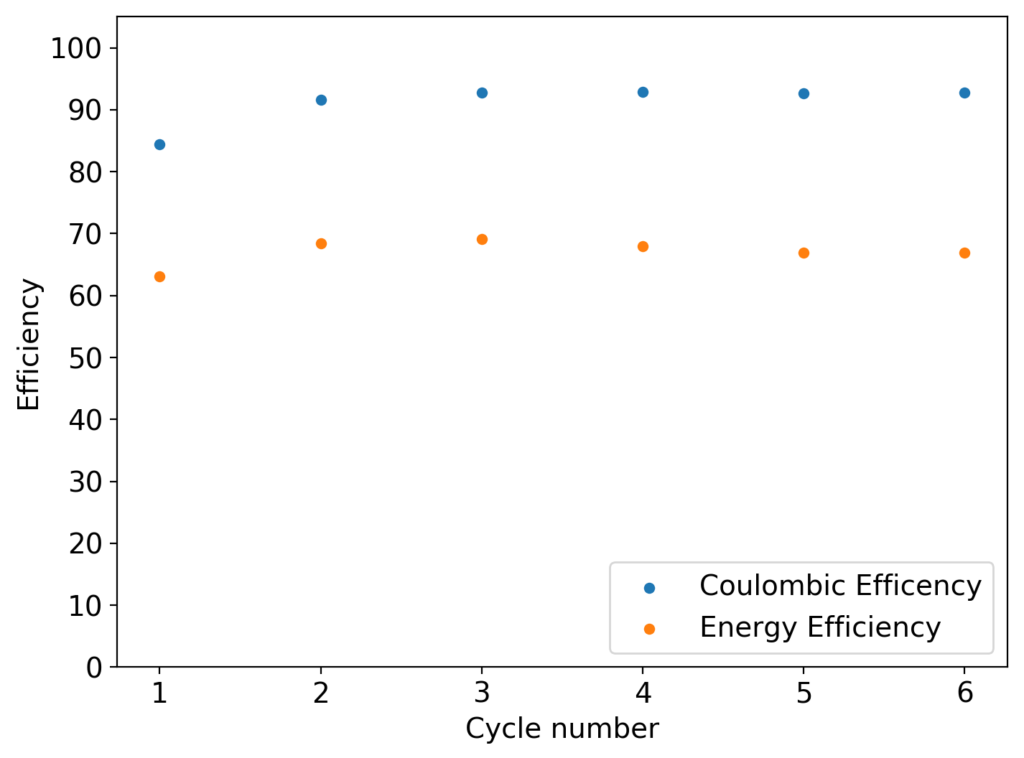
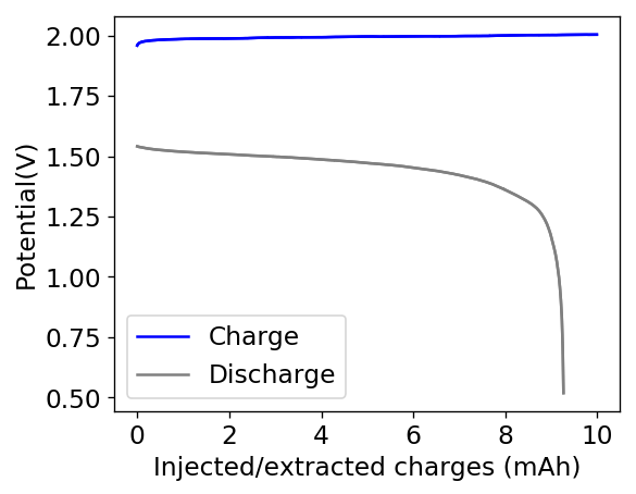
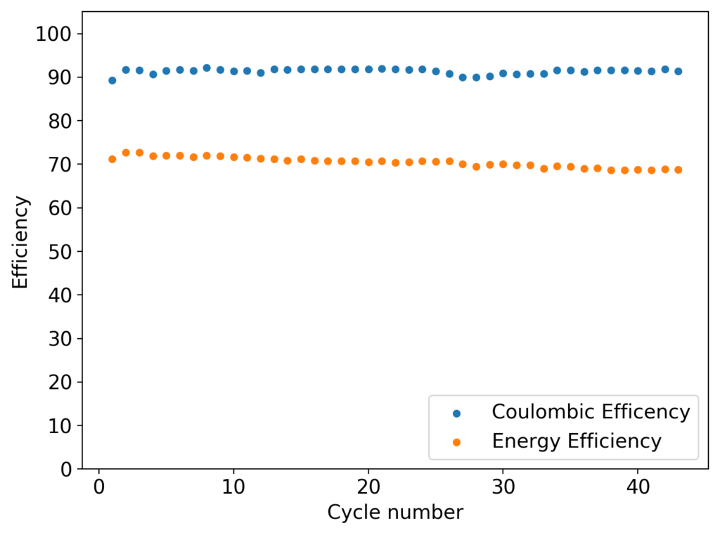
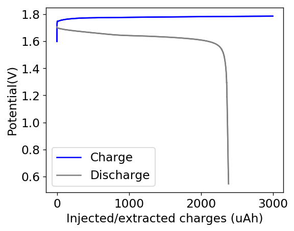
The first prototype battery put together in this configuration – 3M ZnBr2 + 20% PEG-200 solution – has been able to survive 6 charge/discharge cycles, charging to 10mAh and discharging to 0.5V, both at 10mA. The battery has an energy density of 21.6 Wh/L, given its current geometry (all battery components) but I am hopeful this energy density can be pushed closer to 40 Wh/L after I confirm that dendrite formation is not an issue under this electrolyte conditions. Previous batteries in a fiberglass separator were able to sustain 10-20 cycles under these conditions before showing important shorting issues due to dendrite formation, so we will see how far this prototype battery can go before disaster strikes.