Tag Archives: TMPhABr

Zinc Bromine Batteries: Proposing the next scaling level, a petri dish battery

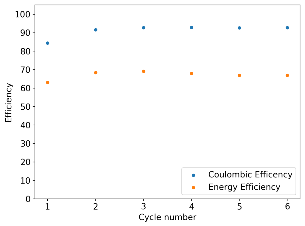
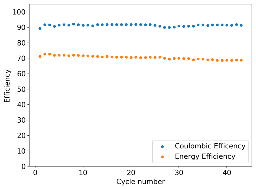
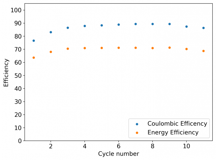
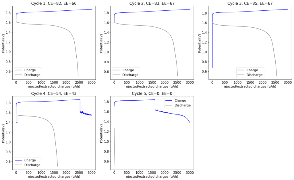
My experiments with Zn-Br batteries in Swagelok cells have now matured to the point where a relatively stable battery has been achieved with no large dendrite problems and acceptable Coulombic and Energy efficiency values (~85% and ~65% respectively). I believe these results would already allow some of you – who want to explore larger scales – to construct some prototypes with my exact configuration, but at a larger scale. In this post I talk about a larger scale setup constructed using a petri dish.

The building material is a difficult choice, since Zn-Br batteries form pretty corrosive chemical species, in particular elemental Bromine and perbromide salts. In order to ensure stability, the cheapest and most easily available material that resists Bromine is glass. The cheapest casing to build a relatively small scale, yet modular and practical battery that fits the geometry of my design would be a petri dish, you can get a 100mm diameter petri dish here, which you could use to put together the battery I’ll be describing.

Suggested geometry for the petri dish cell.

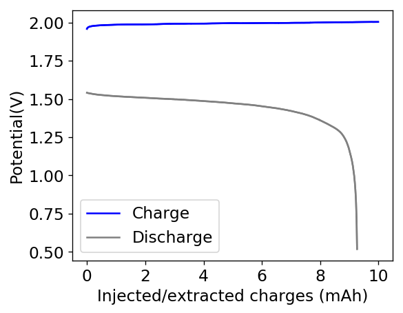
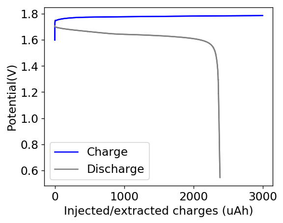
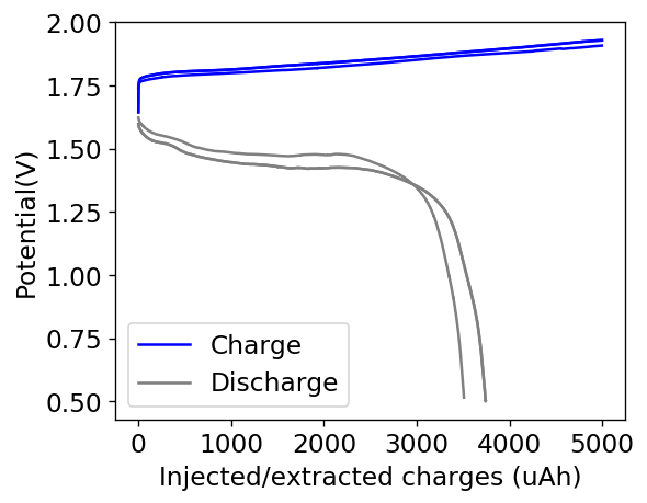
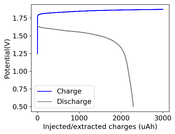
Knowing the area and height of the cell (100mm x 18mm) we can calculate the energy density and charge capacity you should get. Given my previous research, this should be around 2Ah of stored charge with an energy stored of around 2.85Wh. To obtain this ratios you would charge the cell at a constant current of 1A to 2Ah, which matches a current density of around 11.8mA/cm2 in my Swagelok cells, charging to 15mAh at 15mA.

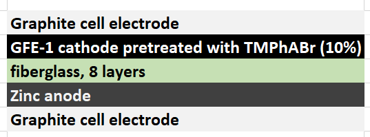
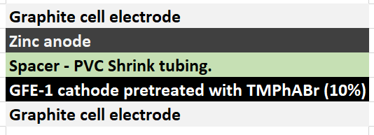
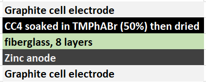
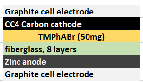
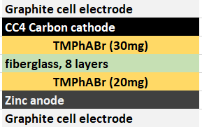
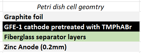
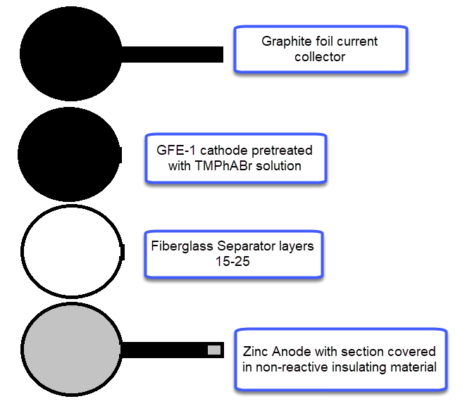
For the anode, you will want to get 0.2mm Zn metal, which you can obtain here. For the cathode you will want to get GFE-1 graphitic felt, which you can buy here. Note that this is NOT a regular carbon felt, it is a highly activated and conductive felt. For the separator a non-woven Fiber glass tissue will do the trick, like this one. The GFE-1 cathode will need to be soaked in a 10% solution of Trimethylphenylammonium bromide (TMPhABr, CAS 16056-11-4) and then air dried. I bought my TMPhABr from alibaba. Using Tetrabutylammonium bromide (TBABr) gives significantly worse results because of the much higher molar mass and lower solubility of the salt in Zinc Bromide solutions. As a current collector for the cathode and to connect it to the outside I suggest you use graphite foil, like this one. For the Zn anode make sure you leave a strip of anode when you cut the piece so that you can make the connection to the outside, cover all the metal that will go through the cell in some non-reactive insultation, electrical tape should work well enough for your first tests so that it doesn’t short with the cathode material.

Geometry of suggested components for petri dish battery

For the electrolyte you can either use Zinc Bromide at 2.7M or a solution of this concentration prepared using Sodium Bromide and Zinc Sulfate Monohydrate. I suggest you browse some of my previous posts on solution preparation if you’re interested in using these sometimes cheaper and more widely available chemicals. However, in both cases you will need to prepare the solution with 3% hydrogen peroxide instead of distilled water, to ensure all Fe is precipitated and removed from the solution before putting it into the battery (Fe impurities cause huge problems in the cells). After preparing the electrolyte, leaving it 24 hours to react and then filtering, drop some strips of Zinc foil in it so that all the peroxide reacts, then use peroxide measuring strips before loading it into the cell to ensure all hydrogen peroxide has reacted. After a couple of days all peroxide should be gone. Also, make sure you also add 1% Tween 20 to the solution, this is a key component to improve wetting and prevent dendrite formation.

To put the cell together, place the Zn foil at the bottom of the petri dish, then cut as many layer of fiberglass separator so that once you put the GFE-1 cathode on top and close the lid you’re able to lightly compress the cell. Then the easiest thing is to take out the separators and cathode, soak them in electrolyte and put them back in the cell. Now you should be able to close the lid, lightly compress it, clean any spillover and seal the petri dish using a couple of rounds of electrical tape.

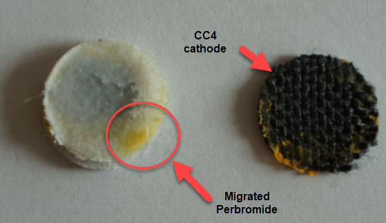
I am also very aware that Bromine is denser and will want to sink into the cell, most of it won’t though as it will be sequestered as perbromide within the carbon electrode. There are very good reasons why this cell has the cathode at the top and why a normal geometry just does not work well for long term cycling at these energy densities. Please read this post to better understand why a practical static Zn-Br battery actually requires an inverted geometry to work well.

Zinc Bromine Batteries: Trying a configuration without a solid separator

During my quest to build and characterize a zinc-bromine battery, I have mainly focused on the use of non-woven fiberglass separators between carbon electrodes in order to hold the electrolyte in the device. This is because some of the research papers with the most promising results for these batteries use this type of separator. Having a solid separator makes the battery easier to construct and easily translates to the construction of both coin-cell and pouch devices, which are the two classic prototype devices used in the modern battery industry. Moreover, a solid separator substantially increases the mechanical stability of the cell and reduced the influence of gravity on the device, making it less susceptible to changes in orientation. The image below details the best structure I have achieved so far for this type of device.

Most successful structure so far for the batteries I have built in my Swagelok cell. Note the cell was never measured in any preferred orientation, the cell was placed horizontally for measuring.

However, one big problem of having a solid separator has been the existence of edge effects at the border of the separator. Batteries have grown Zinc dendrites around the edges of the fiberglass separator, despite my best efforts to attempt to avoid them. While using a 20% PEG-200 concentration and increasing the concentration of Zinc Bromide to 3M helped to largely eliminate dendrite formation, none of these or other modifications were able to fully prevent the problem.

Dendrites formed within a solid separator are quite problematic, because they cannot be fixed and lead to extremely limited battery lifetime. Even if the battery is fully shorted to try to eliminate these dendrites, the mechanical damage to the separator caused by the dendrite structure is permanent, unless more expensive self-healing separators are used. Furthermore, a dendrite can partially react with perbromide coming from the cathode and be cut “half-way” effectively leaving some Zinc stranded in the middle of the battery which is only going to be slowly removed by reactions with diffusing bromine or perbromides.

New battery cell structure I am trying. Note that the batteries are going to be tested in this exact orientation, as the lack of a solid separator means that bromine will accumulate in the bottom electrode, so this electrode has to be the cathode.

For the reasons highlighted above, I have decided to try separator-less batteries in order to see if these batteries can effectively avoid the dendrite problem while still retaining or improving on the coulombic and energy efficiency values I have achieved so far. To do this I have used a 2mm piece of PVC shrink tubing as a separator, cutting it so that it forms a 2mm x 35mm strip that can go around the internal diameter of my Swagelok cell (0.5 inch diameter) and prevent the upper electrode from contacting the bottom electrode. The space is then filled with electrolyte and the cell is closed, with the spacer preventing any additional compression of the cell.

The biggest advantage of this configuration is that it can be easily maintained, since the cell can be opened and the electrodes can be easily changed or cleaned. The lack of a solid spacer also means that any Zinc dendrites that form will either dissolve as they touch the lower electrode or fall and just discharge the battery, while they will never be “stranded” in the middle of the battery. Large amounts of dendrites might still lead to battery shorts, but given that I am using 20% PEG-200 and there are no longer any separator related edge effects, I hope this will stop being a huge problem.

Coulombic and energy efficiency as a function of the charge/discharge cycle for first battery under the above configuration
Charge/discharge curve for last cycle in the previous image. Charge/discharge is done at 10mA.

The first prototype battery put together in this configuration – 3M ZnBr2 + 20% PEG-200 solution – has been able to survive 6 charge/discharge cycles, charging to 10mAh and discharging to 0.5V, both at 10mA. The battery has an energy density of 21.6 Wh/L, given its current geometry (all battery components) but I am hopeful this energy density can be pushed closer to 40 Wh/L after I confirm that dendrite formation is not an issue under this electrolyte conditions. Previous batteries in a fiberglass separator were able to sustain 10-20 cycles under these conditions before showing important shorting issues due to dendrite formation, so we will see how far this prototype battery can go before disaster strikes.

Zinc Bromine Batteries: Trying to improve energy efficiency above 80%

My experiments using carbon cloth cathodes have helped me construct some decent static Zinc-Bromine batteries. In particular, the CC4 carbon cathodes have been very flexible and have been used throughout most of my experiments. The last experiment I did, with a CC4 cathode previously soaked in a 50% solution of TMPhABr solution and then air dried, have shown a CE=91% with an EE=70% at a charge/discharge current of 5mA, charging to 3000 uAh and discharging to 0.5V.

Coulombic and energy efficiencies as a function of the number of cycles for a pre-treated CC4 cathode (soaked in 50% TMPhABr and air dried) with a 3M solution ZnBr2. Charged to 3000uAh at 5mA, discharged to 0.5V.

Charge/discharge curves for all the cycles in the first figure.

Coupling these cathodes with a ZnBr2 3M solution with 10% PEG200 has allowed me to achieve specific power values in the region of 30-40 Wh/kg – total weight of cell – with more than 40 charge/discharge cycles (see above), without the formation of any Zinc dendrites (which would short batteries after only 10-20 cycles at this charge density in previous battery tests). Higher PEG200 concentrations cause significant increases in the internal resistance of the cell while lower concentrations (<5%) are just not effective at preventing Zinc dendrite formation when using metallic Zinc anodes.

Despite the good results, I have yet to achieve high energy efficiencies, mainly due to a couple of problems. The first is that significant bromine diffusion is happening due to a lot of bromine being formed at the surface of the CC4 cathode without enough presence of TMPhABr to capture it and the second, that the internal resistance of the cell was still significantly high, owing to the significant resistance of the CC4 cathode being used.

First charge/discharge curve for a GFE-1 felt electrode, pre-treated with 10% TMPhABr. Charged/discharged at 5mA, charged to 3000uAh, discharged to 0.5V.

In order to attempt to solve these problems, I have decided to change to a carbon cathode that is both significantly more conductive and possesses a significantly higher surface area compared to CC4. My choice material being the GFE-1 carbon felt. For the first test I have soaked a piece of cathode in 10% TMPhABr and air-dried it before use.

You can see the first charge/discharge curve ever produced in this configuration above. The charging potential is already significantly lower than that of the CC4 electrode and the discharge potential significantly higher, both signs of a markedly lower internal resistance. For this first cycle the Coulombic efficiency was 79% while the energy efficiency was 72%. We’ll see if the CE and EE of this battery improves as its cycled and whether or not this cathode leads to more stable cycling than the CC4 cloth electrodes!

Zinc Bromine Batteries: Solid TMPhABr layers are not the answer

My latest efforts to build higher capacity Zinc-Bromine batteries, have focused on the use of solid TMPhABr layers, because the solubility of TMPhABr is very low in the presence of high concentrations of ZnBr2 (2-4M). The idea by doing this was to provide a relatively stable source of TMPhA+ cations that could be taken to the cathode and be used to form an insoluble perbromide as bromide is reduced to elemental bromine and then sequestered by the quaternary ammonium salt.

Evident formation of perbromide oustide the cathode material due to movement of elemental Bromine to the TMPhABr solid layer.

However, the solubility of TMPhABr is too low for this and what happens is that the cathode mainly generates elemental Bromine, which then flows through the battery and is converted – outside the cathode – into TMPhABr3 as it reaches the TMPhABr solid layers. What happens is that the perbromide is fixed outside the cathode, and only the portion that is in contact with the cathode is ever able to be reduced to contribute to the battery current during the discharge phase while the part that is far away from the cathode becomes “dead capacity” and is never able to be regenerated again.

This is evident by looking at disassembled batteries – see image above – where the yellow/orange perbromide is present across the battery separator, showing that elemental bromine was produced, migrated, reacted with the organic ammonium salt to form the perbromide and was then unable to be recovered because of its distance from the cathode. This is also showed by the loss in both energy and Coulombic efficiencies for batteries that use this solid layer at higher ZnBr2 concentrations, compared with the cells that used fully dissolved ZnBr2 0.5M + TMPhABr 0.25M. The Coulombic efficiency drops from >95% to <80% while the energy efficiency drops from >80% to <70%.

New cell structure proposed, using a cathode material that has been soaked in a 50% w/v solution of TMPhABr.

The best way to implement this solid TMPhABr strategy might actually be to introduce this solid within the structure of the cathode material (see proposed structure above). For this I have prepared a 50% w/v solution of TMPhABr (it is extremely soluble in distilled water), immersed two CC4 cathodes into it and I am now waiting for these to dry. Once they are dry I will be able to place them within batteries and run an experiment – without any solid layer – to see if this actually improves the results.

Zinc Bromine Batteries: Problems at higher capacities with TMPhABr

As you saw on my previous post, I was able to generate pretty decent results with TMPhABr when using Zinc Bromide solutions at 0.5M with an addition of 0.25M of this quaternary ammonium salt. However it is pretty clear that at this concentration of Zinc Bromide the specific energy is too low, so I subsequently tried to reach higher efficiencies by trying higher concentrations of Zinc Bromide with a solid layer of TMPhABr (since at >0.5M of ZnBr2 the solubility drops too much). My experiments were done with the cell configuration showed below. The electrolyte also contained 1% of PEG-200 in order to prevent dendrite formation.

Battery structure for tests shown below.
Charge/discharge curves charging to 2000 uAh at 2mA and discharging to 0.5V at this same current. Last value was CE=86.41% and an EE=68.74%. This electrolyte contained a 2M solution of Zinc Bromide.

These experiments were quite successful, with a Coulombic efficiency of 86.41% and an energy efficiency of 68.74%. The capacity of these devices was increased by 4x over my previous experiments at 0.5M of ZnBr2 showing that the solid layer of TMPhABr does work in order to generate insoluble perbromides within the battery. However the battery performance did start to degrade at around the 10th cycle, so I stopped cycling the above battery to see if I could get better behavior at even higher Zinc Bromide concentrations since the increase in ZnBr2 concentration did show a reduction in the internal resistance of the battery.

Charge/discharge curves for a 3M Zinc Bromide electrolye, where an attempt was made to charge to 5000 uAh and discharge to 0.5V at a current density of 5mA. Highest CE=74.71%, EE=55.76%

The attempt to use higher concentrations at higher current densities were not very successful. Although the capacity was increased to around 10x of my initial battery, the problem was that both the Coulombic and energy efficiencies dropped to unacceptable levels. The charging voltage also saw substantial climbs – reaching almost 2V – which probably created a lot of unwanted reactions. The worst problem was however the zinc dendrite formation, which became apparent after I tried cycles at lower capacity and current density for the same cell. You can see below that at the fourth cycle the charge voltage drops suddenly and then the discharge is extremely inefficient. This is because dendrites have pierced the separator effectively shorting the battery.

Curves where I attempted to charge to 2000 uAh and discharge to 0.5V at 2 mA.

This dendrite issue is one of the most important problems in Zinc-Bromine batteries – both flow and static – and one of the reasons why rechargeable Zinc chemistries have not been massively adopted thus far. If the above batteries are to be practical, I need to find a setup that provides both high capacity – which means a 3M ZnBr2 electrolyte – with the elimination of Zinc dendrites. The addition of PEG-200 helps, but it is clearly not enough to eliminate this issue. Upon opening the above battery, it was evident that dendrites had completely pierced through the entire separator and shorted the electrodes.

One hypothesis I have is that local formation of Zinc dendrites should be hindered by high local TMPhABr concentrations (since they do not form when high amounts of this are dissolved) so a potential solution is to create another solid layer of the TMPhABr next to the Zinc anode (as shown below). I am currently testing the battery configuration shown below to evaluate this hypothesis.

Current testing configuration to attempt to remove Zinc dendrites by a much higher local concentration of TMPhABr close to the Zn anode.
Curve for the above cell charged to 3000 uAh and discharged to 0.5V at 2mA. CE=76.51%, EE=61.01%

Another issue that has been pointed out to be is the absence of additional support electrolyte, so I am planning to test ammonium sulfate at 2M to see how this modifies the behavior of my batteries at these higher capacities. Ammonium ions will turn my battery more acidic, so I am expecting some losses in Coulombic efficiency at higher current densities from a more favorable hydrogen evolution potential.