Zn-Br sulfamate battery stability

On a previous post I discussed my first attempts at reproducing the Na-sulfamate based Zn-Br battery published by a group of Chinese researchers. My results showed that the chemistry works mostly as they showed, but I was unable to reproduce both the capacity and stability properties of their testing results. This post summarizes some additional research results I obtained with this chemistry and why, I believe, my results have been unable to match theirs.

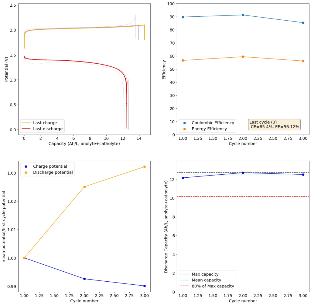
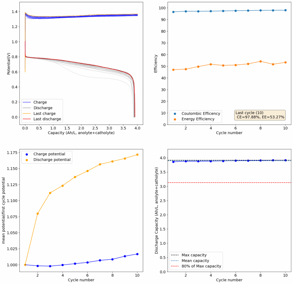
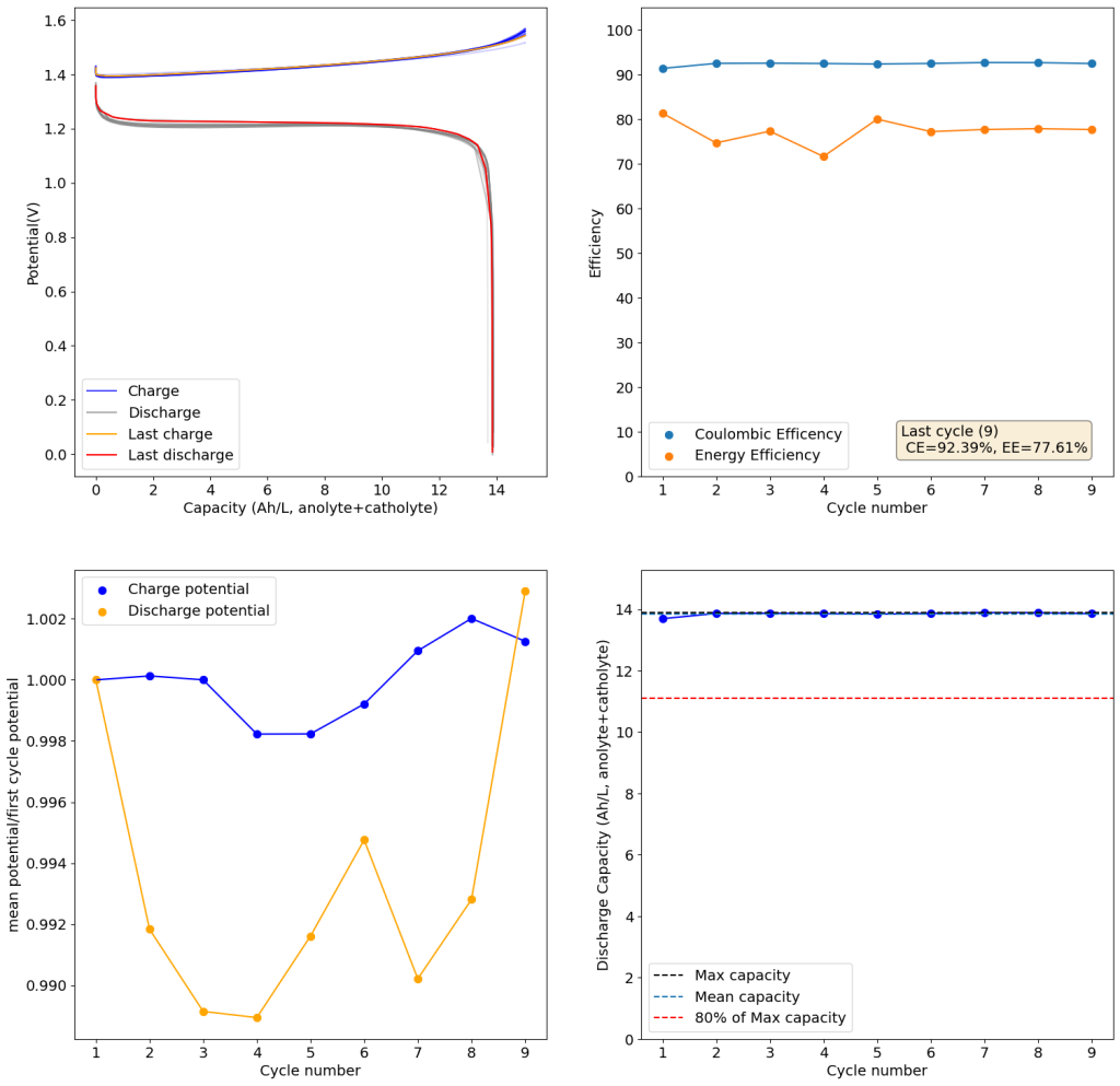
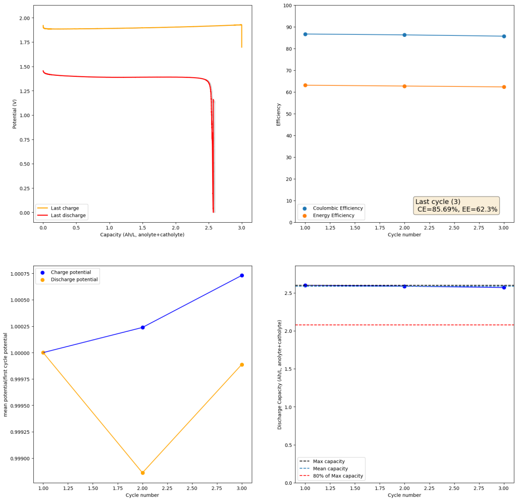
From the get go, my results showed significant declines in capacity when charging to the Nernst limit. This happened even at lower capacities and even at lower concentrations. Oftentimes with deterioration of the charging potential but sometimes with no changes in charging potential at all. This was irrespective of whether the buffer was prepared with just KAc additions, with HAc+KAc or with different buffer strengths. Additional HAc additions did not recover this capacity, which makes me believe that the losses are due to some permanent loss of the sulfamate inventory. Since these losses often happened with very little or no deterioration of the average charging potential, it also makes me believe these are not due to problems with Zn dissolution. After I opened the batteries I also saw no accumulation of metallic Zn on the anode felt or separator (while when it’s a problem with Zn reversibility you see some clear dead Zn remains).

Charging to the Nernst limit (to 2.1V) shows some clear capacity losses as a function of cycling. The above is for a 0.5M ZnBr2, 0.5M KBr, 0.5M Na-Sulfamate solution in a 5 pH buffer prepared with KAc and 8% Acetic acid. 100% SOC would be close to 6.7Ah/L, as the reaction is limited by sulfamate on the catholyte side. Catholyte and anolyte electrolytes are identical on start. 25mA/cm2 current.

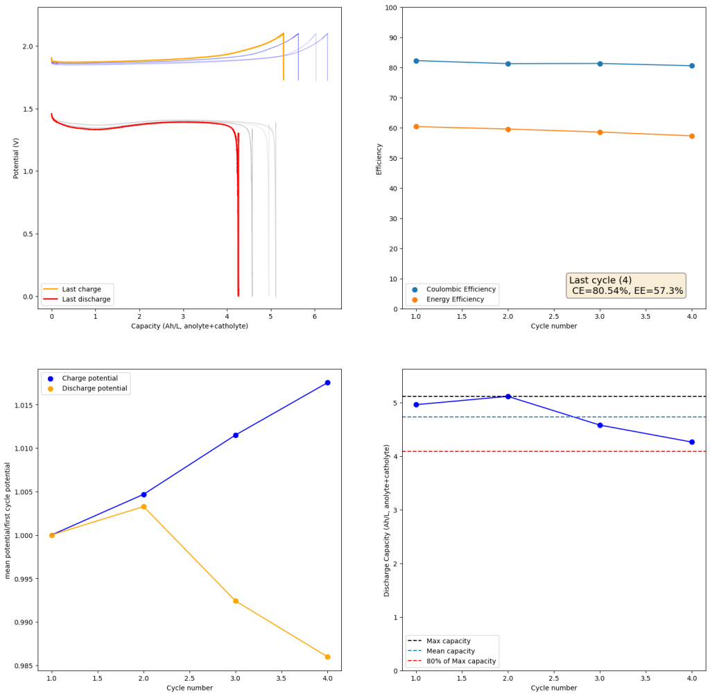
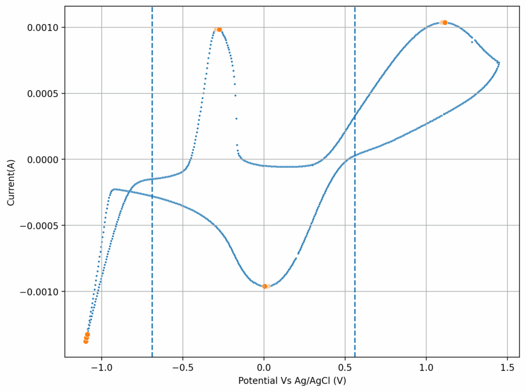
If you read the original Nature paper carefully, you’ll also see that none of their charge curves ever reach the Nernst limit but they are carefully capacity limited to some predetermined value. This initially makes no sense – why would you choose to not use all your capacity? – unless there was a problem with either Zn dendrites or with some other side reaction. Given that Zn dendrites don’t seem to short the battery until much higher capacities, it seems clear that the problem must be elsewhere.

To test this hypothesis I tested the reversibility at 50% of the SOC. It is clear that the deterioration slows down at this point. It is also clear that my cathode – being normal felt – is way less electrochemically active than the carbon nanotube and N-doped felt that is actually used by the Chinese research group. This makes me believe that sulfamate starts degrading at high SOC values, perhaps because N-Br sulfamate starts becoming so concentrated that double bromination becomes possible and then the double brominated N sulfamate is much more likely to decompose with degradation of the sulfamate, possibly into sulfate, ammonium and other brominated side products, like bromate or hypobromous acid. Perhaps the fancy cathode of the Chinese research group has much faster kinetics and is able to handle much faster Br transfers into sulfamate without exposing already brominated sulfamate to double brominations. However, since they don’t charge to the Nernst limit, it makes me believe that they still saw this when they tried charging to higher potentials, hence they didn’t.

Perhaps the most important fact is that capacity recovers if you add more sulfamate, which pretty much confirms that the problem is due to sulfamate degradation.

Same battery as described on the previous image but only charged to 3Ah/L capacity at same current density.

The above implies that sulfamate, while able to support Zn-Br chemistry, is not as stable as it seems on the paper. Careful control over the charged capacity is needed and cathodes that allow very good kinetics for the bromination of the sulfamate are also required. Without significant engineering of the cathode material, it seems that you are limited to around 50% of the SOC – based on the sulfamate – if you want to avoid degradation of the sulfamate as a function of time.

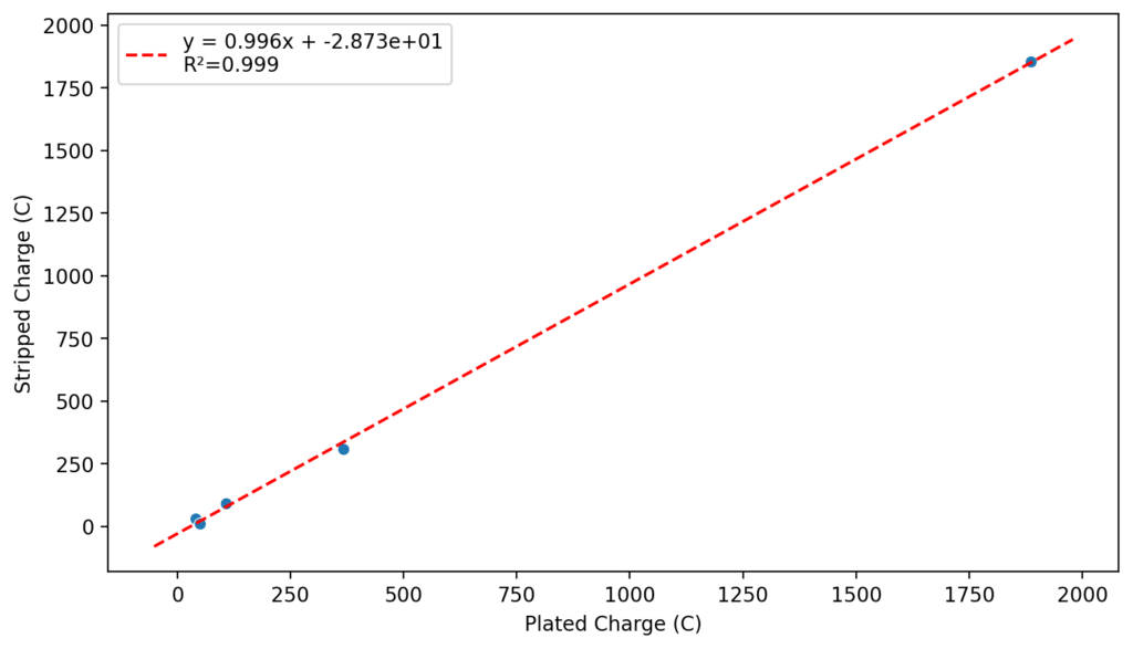
Also, capacities reported by the Chinese group seem to be based only on their catholyte volumes, therefore you have to divide all their values in half if you want to make real comparisons to Ah/L values. They still reach very high capacity values, very close to the actual 100% SOC levels for these systems, although without ever taking the batteries to the Nernst limit. My battery has much higher internal resistance than theirs, which also explains a lot of this difference (as my kinetics are slower, my potential increases much earlier).

Long story short, you cannot just add sulfamate to a Zn-Br electrolyte and expect the battery to work like magic. As it is always the case in batteries, the devil is in the details.

Reproducing Zn-Br flow batteries using Sodium Sulfamate

A recent Chinese Nature paper showed how Sodium sulfamate can be used in Zn-Br batteries to sequester active Br2 into an N-bromosulfamate that is much less aggressive, much more water soluble and even more easily electrochemically reversible than elemental bromine. I also wrote a recent post discussing the potential use of nicotinamide to achieve this (plot twist, it doesn’t work as the nicotinamide Zn complex is not very soluble). In today’s post I want to share with you my attempts at reproducing this chemistry of the Chinese paper using our open source flow battery dev kit.

The paper is very extensive and shares multiple formulations, they share a formulation for normal asymmetric cells as well as formulations to run the batteries using microporous Daramic membranes. Thankfully I have a bunch of 900um Daramic (thanks a lot to Daramic who donated these membranes to us for research). I bought some Sodium sulfamate (NaSA), Zinc bromide (ZnBr2), Potassium bromide (KBr) and potassium acetate (KAc) and proceeded to run some tests.

Tests using 1M ZnBr2, 1M KBr, 2M KAc, 1M NaSA. Charge and discharge were both done at 30mA/cm2.

My tests using the formulations that they disclose exclusively for daramic were not very successful. Formulations using only ZnBr2, KAc and NaSA suffer from either lower capacities because of lower conductivity or issues with hydrogen evolution. This was specially the case when I tried the ZnBr2 1M, KAc 1.5M, NaSA1.5M formulation, which they suggest in the supporting information to reach >50Ah/L. However I think this is a typo and they meant 2M ZnBr2. If you read that paragraph in the supporting information closely you’ll realize why this is the case (they previously refer to a ZnBr2 1M solution and then say this is basically 2x that, but still write it as ZnBr2 1M).

I then proceeded to test using some of the electrolytes they suggest for asymmetric cells, which were much more successful. In particular the 1M ZnBr2, 2M KAc, 1M KBr and 1M NaSA was great, with high CE values and decent EE values (see graph above). I didn’t experience dendrites before reaching the Nernst limit of the cells when using the 900um thick Daramic, which suggests plating is not as aggressively dendritic as with other electrolytes. However dendrites are quite evident when using 300um Daramic, suggesting you need around 300um of Daramic for every 30mAh/cm2. This might explain why the paper restricts most plating to below 90mAh/cm2 when using the 900um Daramic. I have yet to reproduce the Chinese group capacity or cycling stability values, but I believe I have validated the electrochemical principles well.

Clear evidence of dendrites at 78-79mAh (using 8mL of total electrolyte) using a 2M ZnBr2, 1.5M KAc, 1.5M NaSA electrolyte.

It is also worth noting that the Chinese group does some fancy functionalization of their felt with both nitrogen containing groups and carbon nanotubes, which aggressively boosts the conductivity and energy efficiency of the felt for the Br reactions. This is an important different that might justify why they get energy efficiencies closer to 75-80% while mine are just shy of 60%. I also haven’t optimized the compression ratio of my felt, which means that my felt might be under or over-compressed to extract the max EE in this setup. I also lack an oven to properly do air activation of the felt, so my felt is quite suboptimal and just used as-is.

Furthermore, the paper successfully tested a true flow battery setup using Ti-Br. I cannot easily buy TiOSO4 but I decided to try to innovate and test this chemistry in a fully symmetric setup coupled with 0.5M of Fe-DTPA. While Fe-DTPA isn’t expected to be fully resistant to N-bromosulfamate, I figured it might last enough to provide me with some data. Given that the redox potential of the Fe-DTPA redox couple is quite lower than Fe2+/Fe3+, I figured it should give some appreciable voltage in an Fe-DTPA/N-Br-sulfamate battery. Fe-DTPA is also quite soluble and stable at the near neutral pH that favors the N-Br-sulfamate chemistry, so it should work nicely.

Fe-DTPA 0.5M, NaSA 1M, KBr 1M, KAc 1M. Cycled at a current of 30mA/cm2.

The results above, which have never been published before, show that this chemistry works to some extent. The low CE does suggest that a significant portion of the Fe-DTPA is somehow lost, perhaps to oxidation by atmospheric oxygen (I cannot purge my cells with N2 or Argon at the moment), but also likely from just interactions with N-Bromosulfamate across the microporous membrane. With that said, it does show that the new stabilized bromosulfamate chemistry opens up the window to some very interesting options that just didn’t exist before. Perhaps I can test nicotinamide in this setup, where there is no Zn to cause it to precipitate out of solution.

Finally, I wanted to dedicate the above post to Robert Murray-Smith, a fellow chemist in the UK who passed away recently and was a key inspiration for the start of this blog. I know his passing has been very sad for a lot of us in the DIY community, the curiosity and inspiration he instilled in a lot of us will live on. Thank you Robert!

Could we create a Zn-Br flow battery using Nicotinamide?

Zinc bromide flow batteries have been researched very extensively during the past 30 years. There are many advantages to this chemistry, very high potential (~1.8V), high efficiencies, symmetric electrolyte and low reagent costs. Nonetheless, the disadvantages are also huge: zinc dendrites, hydrogen evolution, bromine corrosion, etc. Despite all the development, a lot of these disadvantages remain insurmountable.

A recent nature paper has disrupted the field by using sulfamate ions as a bromine scavenger. Unlike previously used complexing agents that sequestered Bromine as reactive Br3- species, the new scavenging method sequesters Bromine as an N-bromosulfamate, which is stable in solution in the timescales necessary for energy storage. Furthermore, the N-bromosulfamate is chemically much milder than elemental Br2 or Br3-, making the use of cheaper gasketing materials possible and preventing a lot of issues associated with the high reactivity of elemental bromine species.

A model of the nicotinamide molecule. The Br reacts primarily with the amide group (NH2) under mildly acidic conditions.

I have been very excited by these findings and have ordered some sodium sulfamate to test this chemistry myself in our FBRC development kit. However, the development of this technology is likely not open source and it is very likely that the people involved with it want to patent it and lock down the technology. This made me think about potential alternatives that could be used outside of the sulfamate family that could also exploit the mechanism of Br storage in N-Br bonds. Such a technology might be outside the scope of their original paper and therefore be exempt from intellectual property registration.

Thinking about the stability of N-Br compounds (usually not stable at all), I immediately think about NBS and analogous chemical compounds. These are very stable reagents that are routinely used in chemical synthesis, although their aqueous solubility is very low and therefore not useful in the creation of a ZnBr2 aqueous battery.

With that said, nicotinamide (vitamin B3) is a very water soluble and readily available material that also forms a stable N-Br compound in mildly acidic conditions. This 2007 paper describes how N-bromonicotinamide can be created using elemental bromine. While N-bromine compounds from amines like this would often go through a Hoffman rearrangement to yield the corresponding amine, this doesn’t happen under mildly acidic condition in the case of nicotinamide. In fact, the 2007 paper mentions that a concentrated solution of this N-Br compound was stored for months without degradation. The solubility of nicotinamide is also very high (5-6M), compared to sodium sulfamate’s solubility limit of 1.3M at 25C.

An example of a nicotinamide-Zn complex. Check this paper to learn more.

Furthermore, nicotinamide forms mono and dimeric complexes with Zn atoms through the nitrogen in their pyridine ring, which makes this nitrogen unavailable for potential deactivation with direct bromination of this N to yield the corresponding quaternary nitrogen salt (irreversible and undesirable in the context of a battery).

Given that vitamin B3 is very soluble, very low cost, already produced industrially, has a stable amide N-Br compound and is unlikely to undergo Hoffman rearrangement or similar decomposition modes, it is a great candidate to serve as a Br2 scavenger in a ZnBr2 battery. I am going to buy some vitamin B3 to test this idea out. Stay tuned for some tests of this and the sodium sulfamate chemistry.

Studying a WiSE based all-Fe chemistry using our flow battery kit

All-Fe flow batteries are very promising due to iron’s high abundance, low toxicity and low cost. In these batteries, FeCl2 is used as the main active salt in solution. When charging Fe2+ gets reduced to Fe metal on the anode while Fe2+ gets oxidized to Fe3+ on the cathode. However, these batteries suffer from a fundamental problem that has made their large scale adoption very difficult up until now.

Cyclic voltammetry of 1M FeCl2 and 4.5M CaCl2 using an Ag/AgCl reference electrode and a glassy carbon working electrode.

The main limiting problem of these batteries is H2 evolution at the anode. Since Fe plating happens at a lower potential than H2 evolution, there is always some hydrogen generation when the battery is charged. This H2 evolution causes an increase in the pH of the battery which then causes iron hydroxides and oxides to precipitate out of solution. This causes passivation of Fe metal surfaces, loss of capacity and potentially clogging of the battery.

A few years ago, Tao Gao’s group in Utah discovered that CaCl2 and MgCl2 water-in-salt-electrolytes (WiSE) (read the paper here) could substantially improve Fe plating behavior. While they didn’t test this in flow batteries, they showed that very high Coulomb efficiencies with very low hydrogen evolution rates were possible when using these salts. This is because these salts bond with water and therefore make it substantially harder for water to get reduced at the anode. We are talking about very highly concentrated solutions though, around 4.5M CaCl2, which is around 660g/L of CaCl2.2H2O.

Plate/strip experiment using the 1M FeCl2, 4.5M CaCl2 electrolyte.

We recently obtained some of these reagents to test these chemistries in our flow battery kit. I first ran CV experiments of the 4.5M CaCl2 electrolyte with 1M FeCl2 and obtained the curves showed above. This reveals standard potentials of -0.71V and 0.55V for the two half reactions, which means our battery should have a max potential of around 1.26V. I then ran plate/strip experiments (using different plating times), which generated the second curve above. Using the slope of this plot we can extract the plating efficiency, which is >99% in this case. This means that very little hydrogen evolution is happening within this electrolyte, a result I had never seen with FeCl2 solutions and which is in agreement with the Tao Gao group paper.

After doing this I then ran a flow battery using this electrolyte and noticed some problems with capacity loss because of undissolved metallic Fe on the anode using a Daramic separator. It seems that the above electrolyte has some issues with the reversibility of the plating reaction. While little hydrogen is generated on plating, there still seem to be some important losses of capacity due to passivation of the Fe. To fix this problem I then added 1M NH4Cl into the electrolyte, which helped me fix this issue when dealing with Zn-I flow batteries.

Cycling of an all-Fe battery using 1M FeCl2, 4.5M CaCl2 and 1M NH4Cl. Cycling was done at 20mA/cm2 Charging was done to 4Ah/L and discharge was done to 0V.

I cycled the battery at 4Ah/L, which generated the results above. You can see that we get extremely good CE values (97.88%) which are even better than those we were obtaining with the Zn-I system, even though we’re using a microporous separator. The energy efficiency is lower than for Zn-I but still reaches a value of 53.27%. Given a concentration of 1M FeCl2 , 4Ah/L represents a state-of-charge (SOC) of ~30%. The cycling is stable, although some increase of the charging voltage is indeed happening through time (although this is also matched by an increase in the discharge voltage). The mean discharge potential is quite low though, at 0.7V, which means we have considerable ohmic losses at this current density.

I am now testing the electrolyte at higher SOC values and will continue testing MgCl2 and other modifications, such as additions of ascorbic acid and thiosulfate to remove oxygen from the initial solutions and improve the initial state of the battery (as some capacity is lost due to the presence of oxidized Fe in the initial solution). Make sure to follow our progress on this forum thread.

This flow battery kit work is being funded by the Financed by Nlnet’s NGI0 Entrust Fund. We are also collaborating with the FAIR Battery project.

Our v2 Open Source Flow Battery Small Scale Kit is now stable

After a lot of work on our small scale flow battery kit, the kit has now reached a form factor that is stable and will only require minor cosmetic changes from now on (to do things like hide exposed cabling, etc). The instructions for assembly of the kit are available at fbrc.dev. The kit is the culmination of 2 years of hard work from our team at the Flow Battery Research Collective, especially Kirk Smith and Josh Hauser, who both worked tirelessly with me in the design and fabrication of the kit.

Final form factor of the flow battery kit v2.
The back of the kit now features a box for the storage of the Arduino, to minimize the possibility of any solutions damaging the board. In the future we will add some modifications to better route the wiring.

Our final design uses Kaomer KPK200 24B pumps, polypropylene reservoirs and what Kaomer calls “Tygon Chemical Tubing” which seems to be a PTFE lined BPT tubing material. These materials are all compatible with the Zn-I chemistry and are also expected to be compatible with chemistries like Vanadium, Fe-Zn, pure Fe and even non-aqueous chemistries. The 24V pumps are driven using PWM signals coming directly from the Arduino, they also send digital signals back to the arduino that provide us with RPM information. This allows us to control the speed of the pumps quantitatively and achieve more robust experimentation. The mystat software has also been modified to allow direct control of the pumps from the software as well as monitoring of these readings.

Box design for the flow cell educational kit

As you can see above, we have also created a box design for the flow battery kit, which we have titled “Flow Cell Educational Kit” as applications for it can go beyond flow batteries. We may start publicly selling kits sometime in the near future, if there is enough interest from people wanting a plug-and-play solution (especially for academic environments). If you’re an academic researcher, battery enthusiast or professor looking to provide low cost flow battery setups for your students, feel free to let us know is such a kit would interest you.

These are some recent results using the latest kit setup using Zn-I chemistry. This test was ran at 2M KI, 1M ZnCl2, 2M NH4Cl with a 5% Triethylene glycol addition at 60mA/cm2 for both charge and discharge current.

Above you can see some experimental results using the kit and Zn-I chemistry. We are able to reproducibly cycle Zn-I chemistries to very decent SOC values, even though the above tests have been carried out without any nitrogen purging of the system. This is a testament to the robustness of the system and the Zn-I chemistry we are using as a showcase for it.

With all that said, none of the above would have been possible without the support of our financial sponsor for this project, the nlNet foundation. We are ever thankful for all their support in this endeavor. Thanks to them, we are also building a large scale, fully open source kit, that we also hope to release later this year.

This flow battery kit work is being funded by the Financed by Nlnet’s NGI0 Entrust Fund. We are also collaborating with the FAIR Battery project.