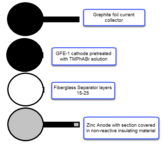
My experiments with Zn-Br batteries in Swagelok cells have now matured to the point where a relatively stable battery has been achieved with no large dendrite problems and acceptable Coulombic and Energy efficiency values (~85% and ~65% respectively). I believe these results would already allow some of you – who want to explore larger scales – to construct some prototypes with my exact configuration, but at a larger scale. In this post I talk about a larger scale setup constructed using a petri dish.
The building material is a difficult choice, since Zn-Br batteries form pretty corrosive chemical species, in particular elemental Bromine and perbromide salts. In order to ensure stability, the cheapest and most easily available material that resists Bromine is glass. The cheapest casing to build a relatively small scale, yet modular and practical battery that fits the geometry of my design would be a petri dish, you can get a 100mm diameter petri dish here, which you could use to put together the battery I’ll be describing.

Knowing the area and height of the cell (100mm x 18mm) we can calculate the energy density and charge capacity you should get. Given my previous research, this should be around 2Ah of stored charge with an energy stored of around 2.85Wh. To obtain this ratios you would charge the cell at a constant current of 1A to 2Ah, which matches a current density of around 11.8mA/cm2 in my Swagelok cells, charging to 15mAh at 15mA.
For the anode, you will want to get 0.2mm Zn metal, which you can obtain here. For the cathode you will want to get GFE-1 graphitic felt, which you can buy here. Note that this is NOT a regular carbon felt, it is a highly activated and conductive felt. For the separator a non-woven Fiber glass tissue will do the trick, like this one. The GFE-1 cathode will need to be soaked in a 10% solution of Trimethylphenylammonium bromide (TMPhABr, CAS 16056-11-4) and then air dried. I bought my TMPhABr from alibaba. Using Tetrabutylammonium bromide (TBABr) gives significantly worse results because of the much higher molar mass and lower solubility of the salt in Zinc Bromide solutions. As a current collector for the cathode and to connect it to the outside I suggest you use graphite foil, like this one. For the Zn anode make sure you leave a strip of anode when you cut the piece so that you can make the connection to the outside, cover all the metal that will go through the cell in some non-reactive insultation, electrical tape should work well enough for your first tests so that it doesn’t short with the cathode material.

For the electrolyte you can either use Zinc Bromide at 2.7M or a solution of this concentration prepared using Sodium Bromide and Zinc Sulfate Monohydrate. I suggest you browse some of my previous posts on solution preparation if you’re interested in using these sometimes cheaper and more widely available chemicals. However, in both cases you will need to prepare the solution with 3% hydrogen peroxide instead of distilled water, to ensure all Fe is precipitated and removed from the solution before putting it into the battery (Fe impurities cause huge problems in the cells). After preparing the electrolyte, leaving it 24 hours to react and then filtering, drop some strips of Zinc foil in it so that all the peroxide reacts, then use peroxide measuring strips before loading it into the cell to ensure all hydrogen peroxide has reacted. After a couple of days all peroxide should be gone. Also, make sure you also add 1% Tween 20 to the solution, this is a key component to improve wetting and prevent dendrite formation.
To put the cell together, place the Zn foil at the bottom of the petri dish, then cut as many layer of fiberglass separator so that once you put the GFE-1 cathode on top and close the lid you’re able to lightly compress the cell. Then the easiest thing is to take out the separators and cathode, soak them in electrolyte and put them back in the cell. Now you should be able to close the lid, lightly compress it, clean any spillover and seal the petri dish using a couple of rounds of electrical tape.
I am also very aware that Bromine is denser and will want to sink into the cell, most of it won’t though as it will be sequestered as perbromide within the carbon electrode. There are very good reasons why this cell has the cathode at the top and why a normal geometry just does not work well for long term cycling at these energy densities. Please read this post to better understand why a practical static Zn-Br battery actually requires an inverted geometry to work well.


