Tag Archives: PEG-200

Zinc Bromine Batteries: Increases in resistance when using TW20+PEG-200 containing solutions

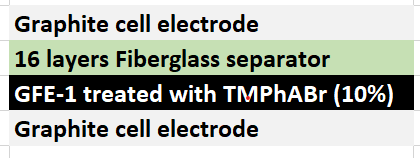
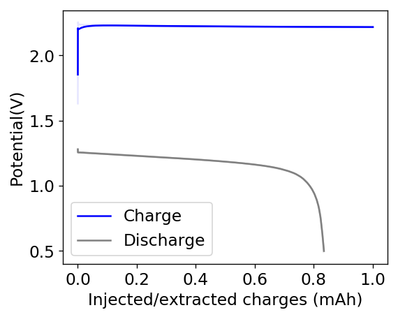
As I showed in my last article on Zn-Br batteries using a Tween20+PEG-200 electrolyte, the batteries had no issues with dendrite production on the zinc anode but faced substantial deterioration of both the charging and discharging voltages as a function of time. I repeated the experiment using a Zinc anode to see if this phenomenon was consistent. The tests below were carried out for a battery that used a GFE-1 cathode pretreated with 10% TMPhABr and an electrolyte containing 1% PEG-200, 1% Tween 20 and 3M ZnBr2. The cell used a 0.2mm Zinc anode and graphite electrodes within the Swagelok cell.

Charge/discharge curves, charged to 15mAh at 15mA, discharged to 0.5V.
CE and EE as a function of the cycle. The cell was run for 8 cycles.

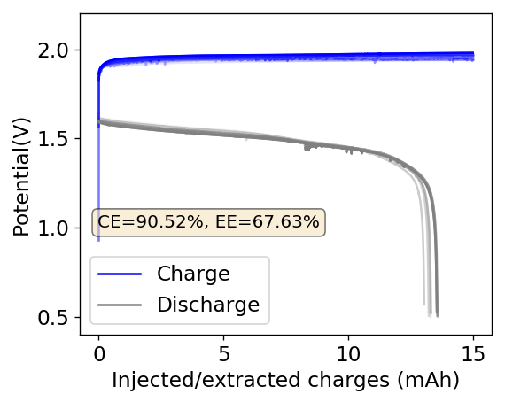
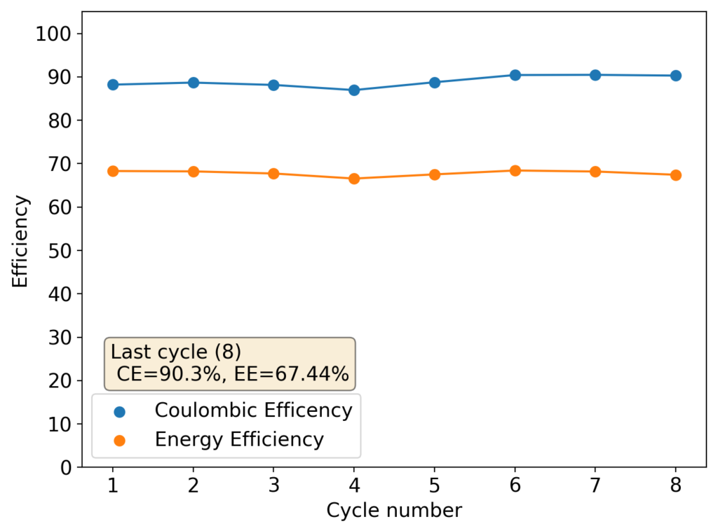
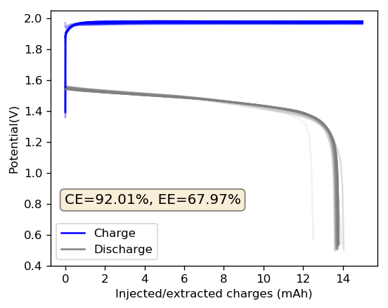
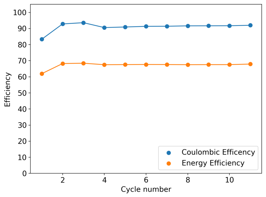
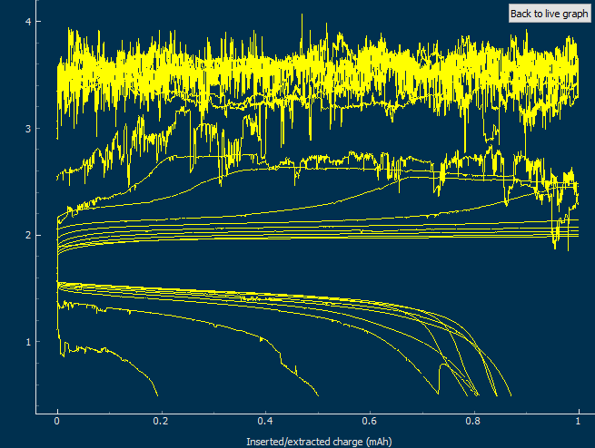
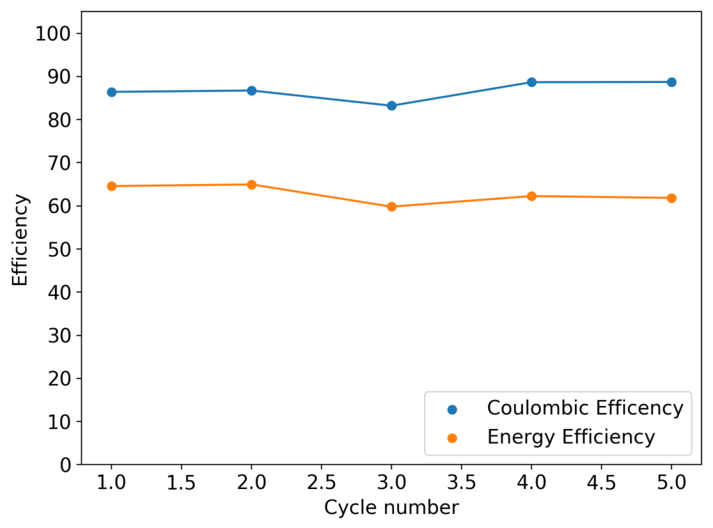
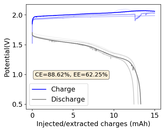
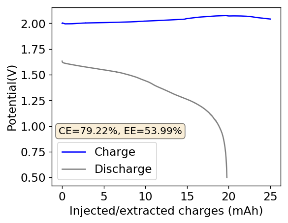
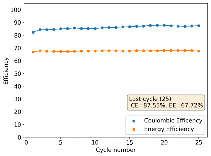
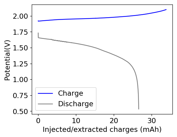
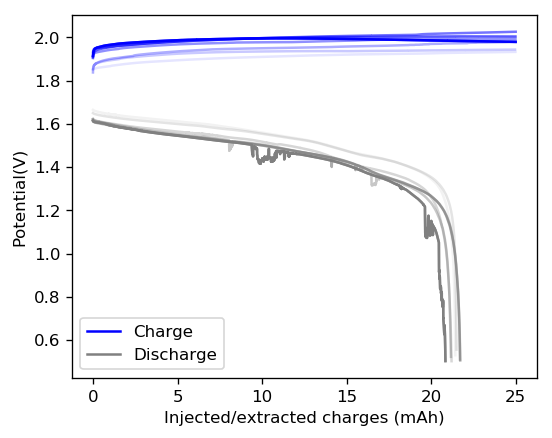
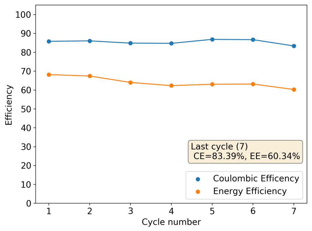
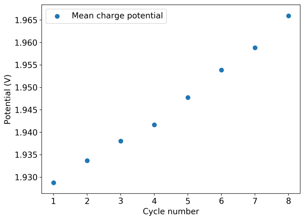
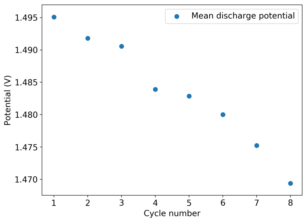
As you can see in the images within this post, although the CE and EE values of the battery remain fairly constant through the test, the mean charge potential increases and the mean discharge potential decreases as a function of the cycle number. This is showing that there is an overall increase in the internal resistance of the cell as a function of time, which appears to be linear and doesn’t seem to become smaller with time. Other cells that were charged to even larger numbers of cycles continued to show this deterioration, up to the point where the EE and CE of the cell started to decay and the cell started to fail.

This behavior points to some irreversible process happening within the device that is fundamentally affecting internal resistance. This has to be either a surface modification of the electrodes or an irreversible loss of conductivity in the solution. The first can happen due to bromide/perbromide interactions in the cathode, zinc oxide deposits in the anode caused by a local increase in pH due to hydrogen evolution or even the appearance of some insoluble polymers in the cathode due to electrochemical reactions of the additives.

Mean charge potential as a function of the cycle number
Mean discharge potential as a function of the cycle number

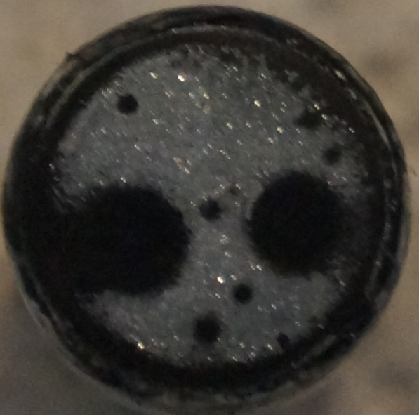
There is some evidence that cathode structure does deteriorate with time under the cell conditions. There is a significant amount of graphite that can be wiped off the Swagelok cell electrode after opening up the cells – while the graphite electrode was sanded and completely clean upon cell fabrication – which might point to the electrode itself or the GFE-1 cathode material degrading. I am currently running an experiment using a titanium electrode with a GFE-1 cathode to rule this out.

About the stability of the additives and sequestering agent, it might be worth it to carry out some cyclic-voltammetry (CV) experiments to investigate the stability of the organic additives being used to see if any of them can fundamentally degrade under these conditions. The TMPhABr could be especially susceptible, given its aromatic amine character. If the sequestering agent can deteriorate under these conditions, then we might be unable to use it as an effective agent and we might need to resort back to TBABr or TPABr. The Tween 20 might also be electrochemically vulnerable, so this additive also needs to be studied in this manner.

Zinc Bromine Batteries: PEG-200 plus Tween 20 to eliminate dendrites, first public results ever!

In the past I have discussed zinc dendrites as one of the most important issues to deal with when creating Zn-Br batteries. While the effect of dendrites can be attenuated by using tall cells with large distances between the electrodes, these setups create high electric resistance that greatly diminishes energy efficiency. A high energy efficiency Zn-Br battery will therefore have the ability to reduce or eliminate zinc dendrites, such that a large number of cycles can be achieved without shorting the battery.

I have studied the use of PEG-200 quite extensively within this blog and although PEG-200 does reduce the formation of zinc dendrites, it also increases the internal resistance of the battery, to the point where the voltaic losses become unacceptable. At useful energy density values (>30 Wh/L) and acceptable charging currents (>10 mA/cm2), the maximum PEG-200 concentration for a 3M ZnBr2 solution is therefore restricted to around 1-3%.

Battery configuration used in the experiments discussed in this post.

Looking at other potential low cost solutions to eliminate zinc dendrites, this article using PEG and Tween 20 in alkaline batteries drew my attention. Although the article used PEG-600, it is reasonable to expect a similar effect with PEG-200, given that this has also been shown to reduce Zinc dendrites in alkaline batteries in multiple publications. It is particularly interesting that they can achieve this with a 0.5% PEG-600 + 0.5% Tween 20 solution, as this would be of practical use within Zn-Br batteries.

To investigate this, I bought some USP grade Tween 20. It is a very safe , non-ionic surfactant commonly used commonly for cosmetics. I then prepared a solution using ~1% PEG-200 and ~1% Tween-20 with 3M ZnBr2. I then assembled a battery as shown above. Note that although I have been using a separator-less setup during the last couple of weeks, I decided to try a fiber-glass based separator setup first, since this setup in the past suffered from dendrites at the edges that I believe might have been caused by surface tension issues with the solution. This problem is likely to be solved by the use of the Tween 20.

First eleven cycles, lighter plots are earlier cycles. Final CE and EE values shown. Charging was done to 15mAh at 15mA, discharge was done to 0.5V.
Coulombic and Energy efficiency evolution as a function of the charge/discharge cycle number.

The solution was easy to prepare and the Tween 20 did not generate any solubility issues. The assembly of the cell was quite interesting, while a 3M ZnBr2 solution (with or without PEG-200) normally takes around a minute to fully wick into the fiberglass separator and the GFE-1 cathode, this time the wicking was almost instantaneous, probably thanks to the use of the Tween 20, that greatly reduced the surface tension of the mixture.

The cycling of the cell is going on without any issues. After around 3 cycles, the magnitude of changes in the shape of the curves and capacity started to become smaller and smaller, with the battery currently settling at a CE ~ 92% and an EE ~ 68%. The total amount of charge extracted is around 13.8 mAh with an average potential of 1.46V, putting the energy density of the battery at this current density at around 30 Wh/L. I am so far amazed at the stability of this battery configuration with few aberrations showing in the charge/discharge curves and no signs of dendrites (so far). The above are the first ever published results – as far as I know – for a Zn-Br battery containing both PEG-200 and Tween 20.

An important early sign of dendrites is a decrease in the charging potential with time – as the zinc dendrites effectively enhance the surface area of the anode before shorting the battery – an effect that I haven’t observed after 11 cycles. Although still too soon, the above results are certainly encouraging, hopefully the synergistic effect between PEG and Tween 20 applies to the Zn-Br system as well.

Zinc Bromine Batteries: Dendrites, adhesion and failure

This past week I did not post any new results for Zn-Br batteries. This is because I started to face significant reproducibility issues in my spacer based batteries with no separator. The image below shows you some of the typical curves I was getting from my batteries using PEG-200 containing solutions at a ZnBr2 concentration of 3M with different NaCl or NaBr additions. The battery started just fine – with CE values close to 90% – but fell sharply thereafter, with big increases in series resistance follower by large losses.

Screenshot taken from the measuring software I am using. This is cycling a battery to only 1mAh of capacity, the battery resistance starts to get higher and eventually fails very aggressively.

After a lot of investigation, the problem seems to be the adhesion of the Zn deposits to the anode’s graphite electrode. Even though the anode is always polished before every battery, the Zn deposits sometimes just “fall off” and – since there is no separator – that Zn falls to the cathode and is thereby lost and simply reacts slowly with the bromine. This was confirmed by moving again to a Zn metallic anode (0.2mm thickness) which didn’t show the above problems, as you can see in the curves below.

Although relatively normal CE and EE values were achieved for this battery configuration, dendrite formation was evident, both in the charge/discharge curves and after taking the battery apart (where dendrites were quite large). It is clear, both from NaCl and NaBr experiments, that additions of these supporting electrolytes contributes heavily to dendrite formation. It also seems pretty clear that going from 1% PEG-200 to 6% PEG-200 or higher doesn’t help enough with dendrite formation – they still form, even if a bit slower – but the heavy increase in series resistance is not worth the trade-off. If you try to add more PEG-200 and reduce the series resistance with NaBr or NaCl, then you just get the dendrites again.

3M ZnBr2 battery with a 1.7M NaCl and 6% PEG-200 addition. Charged to 15mAh at 15mA, discharged to 0.5V. Zinc anode (0.2mm) and GFE-1 cathode pretreated with 10% TMPhABr.

From these experiments, it is now pretty clear why commercial ZnBr2 batteries do not use PEG-200 as an additive – at least in very large quantities – it might work to suppress formation of Zinc dendrites at lower ZnBr2 concentration (<1M) but at the concentrations required for energy density values greater than 30-40 Wh/L it just doesn’t seem to work well enough. Furthermore, while PEG-200 can be used with little effect in highly conductive KOH solutions that are used in some Zn chemistries (like Zn/Mn oxide batteries) it just doesn’t work when the electrolyte’s conductivity is significantly lower, such as is the case with ZnBr2 solutions.

All hope is not lost though. While PEG-200 by itself might not be able to prevent dendrites in this configuration, it is possible that low concentrations of PEG-200 plus other additives might have a synergistic enough effect to help us alleviate the problem. One such potential case is with the use of PEG-200 and Tween-20, which at 0.5% each, have shown to be both quite effective and synergistic at reducing Zinc dendrites. The experimentation continues!

Zinc Bromine Batteries: PEG-200, bubbles and over-potential

In my latest separator-free cells that use a PTFE o-ring spacer, I am now testing some additives to reduce dendrites and increase the life of the cells. A popular additive – PEG-200 – has proved not to be viable at a concentration of 20% due to large losses in the cell’s voltaic efficiency, moreover PEG-200 at a concentration of 1% offers little protection against dendrite formation. This last experiment tried a PEG-200 concentration of 6%, coupled with a small amount of NaCl to attempt to increase the conductivity and compensate for the loss caused by PEG-200.

Charge to 25mAh at 15mA, discharging to 0.5V. Electrolyte contains 0.1M NaCl, 3.0M ZnBr2, 6% PEG-200

Above you can see the charge/discharge curve measured for this device. Compared to my previous devices the Coulombic and energy efficiencies have dropped significantly, with the most dramatic drop being in the energy efficiency. This value has dropped more than 10% relative with previous devices using a 1% PEG-200 concentration at the same zinc bromide concentration.

A device with this energy efficiency will not be viable, so I saw no need to cycle the battery multiple times. However to answer the question of whether zinc dendrites are formed or not, I then charged the cell a second time to 25mAh and opened the device, taking the picture of the anode shown below (I apologize if it seems out of focus, it wasn’t very easy for me to focus on such a small amount of space with my camera).

Graphite anode after one charge/discharge cycle and a subsequent charge cycle to 25mAh.

The picture above shows some interesting results. First, it was evident that there was absolutely no zinc dendrite formation, the plating was very crystalline and the electrode was flat with no protruding dendrites. Previous cells that had dendrite related failures show very tall dendrites that can easily be seen with the naked eye, even after only a few cycles. However you can also see several big and medium holes in the electrode where absolutely no zinc was deposited, this was caused by “air bubbles” trapped when the Swagelok cell is closed, which I haven’t been able to find a method to consistently remove. These bubbles remove so much of the surface area of the electrode that they can be responsible for significant losses in voltaic efficiency. Pre-wetting the electrode seems to be a viable method to ameliorate the issue but isn’t perfect.

In order to see if a cell like this can be viable, I am now testing a 6% PEG-200, 3M ZnBr2, 1.7M NaCl electrolyte, which should dramatically reduce the voltaic losses caused by the PEG-200 by increasing the conductivity of the electrolyte. Stay tuned for these results.

Zinc Bromine Battery: Teflon o-ring separators, capacity and PEG-200

In my previous post, I described my first tests of separator-less batteries using a PVC spacer. This turned out not to be a very good idea, due to the reactivity of PVC with bromine. Although the battery was able to run for 20+ cycles successfully, a lot of noise started to happen within the measurements. After opening up the battery, it was evident that the separator had degraded (it turned from black, to a whitish gray color). Due to this reactivity I decided to change my plans to work with Teflon o-rings as spacers (which I bought here). These are of the exact diameter I needed. Given the height of the spacers, I decided to use 3 (total height of 5.2mm) in order to match the same height of the previous cells I was building using fiberglass separators. This gives a total battery volume of around 0.68mL, counting the volume of the separators.

Battery built using PTFE spacers, GFE-1 cathode pretreated with 10% TMPhABr + 3M ZnBr2 + 1% PEG-200. Charged to 15mAh at 15mA, discharged to 0.5V.

The results for the first battery tested using this configuration is shown above. The energy density of this battery is around 30Wh/L and I was able to cycle it at this current density and charge capacity for 25 cycles without running into any problems or instabilities. At this point I decided to test what the maximum capacity of the battery could be, by charging the battery until the potential reached 2.1V.

With this test I was able to charge the battery to a capacity of around 60Wh/L, but this capacity usage is not sustainable given that the battery completely died on the next cycle due to the formation of a large amount of Zinc dendrites. This means that the usable capacity under this amount of 3M ZnBr2 electrolyte is likely to be around 75% of this value – given what we know from published research and patents – which should be at least 25mAh.

Maximum capacity test charging the battery until potential reached 2.1V at 15mA. We were able to recover 26.56 mAh discharging to 0.5V.
Charge/discharge curves of a battery with the same configuration charging to 25mAh at 15mA, discharging to 0.5V. Notice the instabilities on discharge.
Evolution of efficiency variables as a function of the cycle for the battery shown on the previous image.

After building another battery and charging to 25mAh – taking the energy density to ~45 Wh/L – there were substantial instability issues appearing on the discharge curves after 7 cycles. I believe these instabilities are due to Zn dendrites that fall from the anode into the cathode, temporarily killing the discharge potential of the device until the Zn dendrite is dissolved. These instabilities are correlated with loses in both the Coulombic and energy efficiency values of the battery, deteriorating the performance as a function of time.

Due to the above issues, it seems important to try to reduce dendrites to prevent problems at these capacities. I decided to try a PEG-200 additions at 20% to see what would happen. With this configuration, a 20% PEG-200 addition generated too much voltaic loses because of the huge increase in internal resistance. Even when charging/discharging to only 1mAh, the necessary potential was already above 2.15V, with the energy efficiency dropping below the 35% mark. You can see one such cycle in the image below.

Battery built with a 20% PEG-200, 3M ZnBr2 electrolyte. Otherwise identical to other batteries shown in this post.

Because of the above results, it is clear that a PEG-200 addition is likely going to need to be below the 10% mark in order to be viable. I have since prepared an electrolyte comprised of 3M ZnBr2, 6% PEG-200 and 0.1M NaCl in order to see what the behavior is when trying to charge to these higher capacity values. Up until now charge potentials at 15mA are higher than for the 1% PEG-200 cells, but low enough (2-2.1V) to prevent heavy voltaic loses. We’ll see what sort of efficiencies and Zinc deposits we can get with this electrolyte configuration.