After concluding my work with the Fe-Mn system, I still wanted to find a system that I could use to build flow batteries. With my new flow battery systems – which I got thanks to my colleague Kirk – I have been able to test different chemistries to come up with the most practical approach for an actual DIY flow battery.
To build such a battery, I first started with a list of requirements:
- Easy to find chemical supplies.
- Voltage at least equal to vanadium flow batteries (>1.2V).
- Energy at least equal to vanadium flow batteries (>25Wh/L).
- Efficiencies at least equal to vanadium flow batteries (>70% EE).
- Mildly acidic or basic (no strong acids or bases).
- Ideally uses a microporous membrane (no need for ion exchange membranes).
- Long term cycling stability (>1000 charge/discharge cycles).
There aren’t a lot of systems that can comply with all the above requirements. One of the few that seemed plausible was the Zn-I system. In this system, Zn2+ is reduced to Zn metal on the anode and I- is oxidized to I2 (which quickly gets converted to I3–) in the cathode. The Zn can be plated with a good density, often at more than 100mAh/cm2 of cathode when using carbon felts.
Both the Zn/Zn2+ and I–/I3– couples are kinetically very fast – allowing for large currently densities – and have large energy densities. In particular, the solubility of their salts is quite large, so achieving solutions with concentrations >6M is not a problem. At 6M, the theoretical capacity of the battery is around 156Ah/L, rivaling even LiFePO4 batteries.
There are two main problems with this system. The first is the formation of Zn dendrites in the anode, which shorts the battery, and the second, the formation of solid I2 in the cathode after a state of charge of around 66%, which interrupts flow through the battery and causes it to fail. This means that the max State Of Charge (SOC), is often limited to 66% even if no dendrites are present (which is a big if).
Luckily some publications already exist showing that we can sacrifice some efficiency to overcome some of these issues. For example, this paper uses a polyolefin microporous membrane to obtain flow batteries that work at very high current densities and which can “cure” from overcharging due to the constant “leak” of iodine into the anode side. Since the same electrolyte is used as catholyte and anolyte, there is no problem with changes in composition as a function of time.
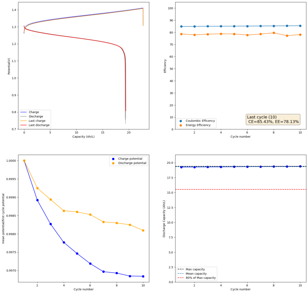
I decided to use this paper as a template and try reproducing their results. I started by making a 2m solution (this is moles of solute per kg of solvent). You can see my results in the first image above. I was able to obtain a charge of 19.3Ah/L since the 2m solution comes out to approximately 1.5M (because the final volume is larger), this comes out to an SOC of 48%. Trying to charge the battery higher ends up generating I2 solid in my cathode and therefore killing the battery (as no flow becomes possible).
My current was also lower (40mA/cm2 vs 80mA/cm2) because my potentiostat overheated at higher densities (which means I need to build some heatsink to test these current levels). Note that I also ran at higher mL/cm2 since my closed loop is exactly 1mL/cm2 while the paper runs at half of this, meaning that their Zn accumulation per electrode area is half. I also used 4 layers of Daramic to match the thickness of their polyolefin membrane (around 900um).
The CE and EE values are pretty decent, but loses from crossover of the microporous membrane are evident. These loses have an advantage though as iodine that permeates the membrane dissolves any Zinc dendrites that might be perforating it, so the battery cycling is very stable.
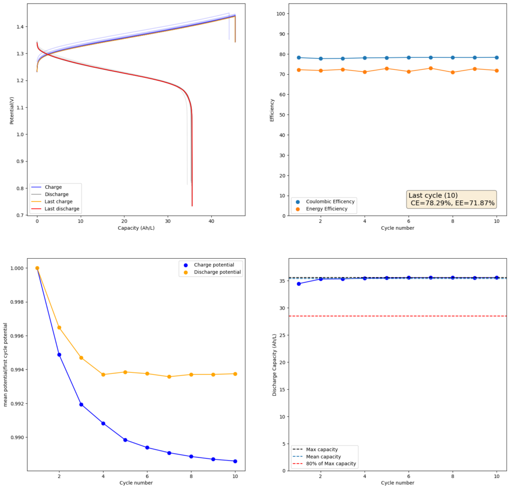
Since I didn’t observe any gain in SOC due to the presence of the Bromide, I tried to reproduce the results using a lower cost mixture of ZnCl2+NH4Cl+KI. This time I also increased the concentration to 4m to see if I would get a proportional gain in the capacity. The results of this test are showed in the second image in this post.
As expected, there is a drop in the CE and the EE of the device (as more crossover can happen at longer charging times) but the capacity of the battery increases proportionately as well. I was able to charge to double the amount, but the discharge capacity did not increase as much, due to the drop in efficiency. This time I was able to get 35.5Ah/L out of the battery, which is an SOC of around 42%. This is however, already higher than a Vanadium flow battery normally offers (~25Ah/L). Note that higher concentrations are not possible in my system with 4 layers of Daramic as dendrites will start fully crossing the separator at a density of around 56mAh/cm2 (while charge density in the last test is 45.45mAh/cm2).
As you can see, the Zn-I system with a microporous membrane is great. It is stable, has decent energy density, supports large currents and does not require an expensive ion exchange membrane. There are certainly potential improvements to increase the available SOC, but even at the current levels, the system would already be useful in practical applications. Higher separator thickness could also increase the CE and EE of the battery system, without much compromise to the ohmic resistance. Small modifications to the separator – such as adding a carbon coating – can also increase its selectivity and reduce the extent of Iodine migration. Note that you do not want to completely stop it as stopping it leads to dendrites shorting the battery.
I also tested some other microporous membranes that could be easier to obtain than Daramic. Interestingly enough, photographic paper – which has a pore size similar to Daramic – works just as well in this system (really cheap as far as membranes go). I will share the results of these tests in a future post.
Pingback: A Zinc-Iodide flow battery using a matte photo paper membrane | Chemisting
Dear Daniel,
This is another test. Two longer posts I prepared seemed to be gone.
It is already possible to share your recipe for the Zn-I flow battery you described above?
I’m looking for an affordable alternative for redflow ZBM3.
regards,
Arend
All comments need to be approved so please don’t worry if you don’t see a comment right after you submit. I am not sure what you mean about a “recipe”, the information needed to reproduce is available in the post. Please feel free to ask about any specifics that might not be clear.
Hello Daniel,
I’m looking for an affordable (DIY) battery which is sustainable. I have already 18 pv panels connected to 3 different inverters. I live in a village in the Netherlands. I want more self-consumption and some black-out proofing. We have a good insulated house with heat pump (4kW). No natural gas connection any more.
What is your opinion about the redflow ZBM3 battery. Can we DIY it a lot cheaper or not?
From your article above i cannot make a ‘household battery’. Maybe you refer to the paper ‘A Long Cycle Life,…’ as they built a 700W output ZIFB?
Arend
Thanks for your reply! So far we are establishing the base line for the Zn-I chemistry and we are going to be building an open source kit so that people can get their own small scale setups for research and micro scale testing of flow batteries. We hope to make the first workshop in the Netherlands in March next year to showcase the first kits and teach some groups of people how to use them. Let me know if you would be interested in attending. These kits are not intended for practical storage but for research and prototyping of chemistries (they are in the mWh scale, so a few mL of solution with a few cm2 of electrode area). To design and test systems in the kWh scale we are going to probably need 2+ years of work. There are many intricacies to building a kWh system, such as the plumbing, pumps, assembly, BMS, etc.
Our objective is indeed to show how to DIY flow batteries in the kWh scale, but it will take time!
Hi Daniel,
Thank you. Can you please answer my questions.
– do you expect we can DIY a redflow ZBM3 battery lookalike in the future a lot cheaper than the price I have to pay now for it (about €10000 for 10kWh storage)
-can I make the 700W output ZIFB from the paper ‘A long life cycle,…’ ? At what price?
Arend
Thanks for writing. Here are my replies to your questions:
1. This is likely but it will take us around 5 years to get to that point. I would say at least 2 years to get to 1kWh, then another 2 years to get to one order of magnitude higher.
2. I don’t have experience at this scale yet. Everything we have done has been in the mW range so far. There are challenges moving onto the watt scale, but I will have some answers for you within the next year.
I hope this helps!
I did a small donation for your FBRC at opencollective. It seems that the bank transfer needs some time.
Thank you very much for your donation!