Over the past year, I’ve collaborated with my colleagues Kirk Smith, Sanli Faez, and Joshua Hauser on developing an open-source flow battery design and kit. Our aim is to make it feasible for most individuals to construct this flow battery with readily available parts that can be either purchased online or fabricated affordably. We’re targeting a price point below 1000 EUR, inclusive of the potentiostat, to ensure accessibility.
The kit encompasses all necessary components for constructing and utilizing a flow battery for research and development purposes. This includes the battery itself, pumps, electronic components for pump operation, potentiostat, tubing, reservoirs, and a jig for orderly arrangement. Presently, similar setups cost upwards of 9000 EUR, hence our aspiration for significant cost reduction.
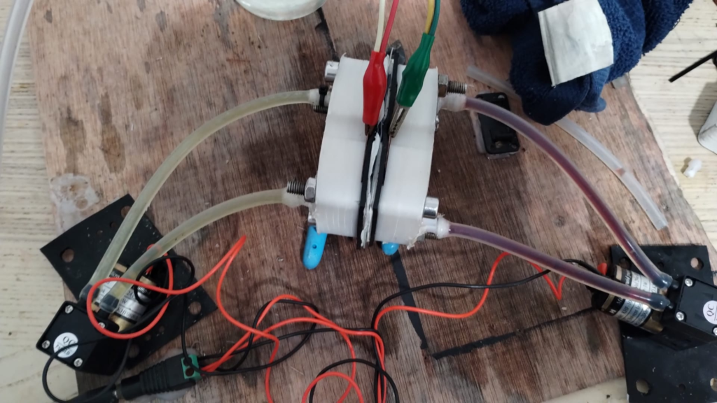
A polypropylene FDM printed prototype being tested with Mn/Fe chemistry. This particular test was done without reservoirs, on close circuit circulation to easily detect any leaking.
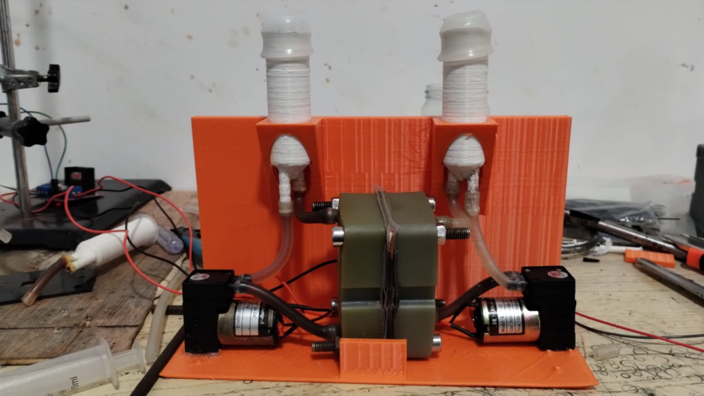
Image of one of our latest prototypes. This features polypropylene FDM printed reservoirs, a resin printed cell body and a PLA FDM printed jig.
Throughout this endeavor, we’ve explored various fabrication methods for our designs, employing FDM and resin 3D printing techniques alongside traditional CNC fabrication. While all three methods are viable, our experiments indicate that the most optimal results are achieved through traditional milling.
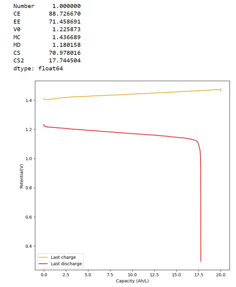
Charge/discharge cycle using photopaper separators and the Zn-I chemistry using the open source flow battery design.
Validation of our design involved utilizing a low-cost photopaper separator and Zn-I chemistry. We’ve achieved successful charge/discharge cycles at capacities ranging from 20-40 Wh/L. However, long-term cycling validation remains ongoing, as we’ve only been testing the final design for approximately a month.
Our design will be presented at the Flow4UBattery Event in Eindhoven, Netherlands, on April 8-9, 2024. You can register here for free, which also includes complimentary lunch (so please make sure you intend to attend if you subscribe). Day 2 of the event will feature a workshop where participants can assemble a flow battery themselves using the design from our kit. Additionally, we’ll be giving away 5 complete kits during the event, each including mystat potentiostats. We’ll also have a fully assembled kit doing cycling so that you can see the fully assembled kit in action!
After this event, we will look into selling these kits online, with all proceeds going towards the development of higher capacity kits with the objective of reaching an open source flow battery stack within the next 2 years. We will also be publishing the full designs and bill of materials online, so that anyone can create their own too!
During the past couple of weeks I have been working on cation exchange membranes using PVA/cellulose (see here, here, here). The idea is to create a membrane that can replace Nafion in a pH neutral flow battery built using an Fe anolyte and a Mn based catholyte. In this post I will share the first results that are up to par with those of a Nafion membrane.
My initial idea was to both crosslink and add anionic sites to the PVA by using phosphoric acid with urea as a catalyst, heating the membrane to >150C in order to perform the esterification process. This worked to a decent degree, achieving membranes with permselectivity values above 80% with sheet resistance values around 10x those of Nafion membranes.
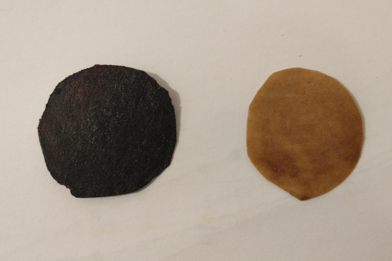
Membranes annealed at 150C (left) and 100C (right)
However there were some obvious issues with this process. The first is that the membranes produced had some stability issues, their permselectivity would drop with time – due to lack of enough crosslinking – and the mechanical stability of the membranes also left a lot to be desired. Both of these issues were likely due to limited crosslinking of the membranes, as forming a double phosphoric acid ester is not a very favorable process, even in the presence of urea.
I would see Fe-EDDHA-1 leak across the membrane within around 24 hours of setting up my cells, with the transparent side turning a slight pink within that timeframe. The permselectivity would also drop from 80% to around 40% within that timeframe. It was obvious that these membranes had components that were still dissolving or at least creating cavities that allowed too much water to flow through.
Thinking about this, I searched for possible crosslinking agents to enhance the issue. I also wanted to avoid usage of anything toxic, like glutaraldehyde, as the space where I carry out these experiments has limited ventilation, plus I want to avoid exposing myself or my cats to harmful substances. Expensive substances were also out of the question, like sulfosuccinic acid.
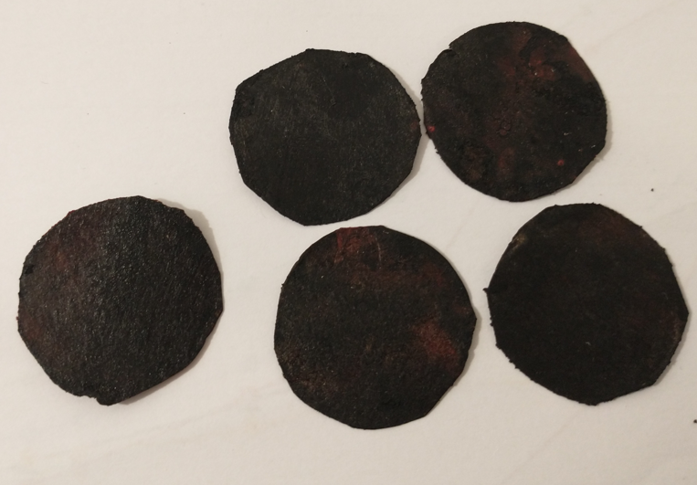
Multiple results of membranes being prepared using this method (each one is around the diameter of a 25c US coin)
Reviewing papers on the subject, citric acid appeared to be a viable substance. It is a tricarboxylic acid, so it would be able to crosslink cellulose with PVA, PVA or cellulose with themselves and also keep some exposed anionic carboxylic groups to provide cation exchange capacity. Adding phosphoric acid would also catalyze the esterification reaction plus also provide some phosphorylated sites for enhanced permselectivity.
The process for preparing these membranes is as follows:
Prepare a solution by adding 15g of PVA to 200mL of water (solution A).
Place solution A in a fridge for 48 hours, with occasional stirring/shaking. Surprisingly, cold conditions are much better for dissolving PVA because they discourage agglomeration.
Wait till solution A is fully homogeneous, keep longer in fridge and shake/stir as needed.
Prepare another solution by using 0.5mL of phosphoric acid (81%), 0.5g of citric acid and 15mL of solution A. This solution is stirred until everything is completely homogeneous (solution B).
Dip a filter paper in Solution B. I used Stony Lab 101 but other fine grain filter papers should work just as well. Make sure all excess has dripped off and tap with paper towels to remove any excess.
Place on a hot plate at 80C for 3min
Flip it to the other side for another 3 minute.
Use a brush to paint solution B on the filter paper while on the hot place.
Wait for 3 minutes.
Flip the filter paper and paint the other side, wait another 3 minutes.
Repeat steps 8-10 three times.
Increase the temperature to 150C.
Flip the membrane every 10 minutes for one hour or until the membranes appear fully black. Put a petri dish on top if needed to keep the membrane flat.
Allow the membrane to cool to room temperature.
Place the membrane in a solution with 10g/L of potassium or sodium carbonate to neutralize any remaining acid, they can be stored in a 0.5M NaCl solution.
The membranes that result from this process are black in nature. However they do not feel like charcoal and do not crumb easily. Instead, they have the feeling of a piece of plastic film, which is exactly what we are looking for. Several papers discussing citric acid crosslinking of different polymers do have resulting black films, so this isn’t necessarily a bad thing.
I was also very pleasantly surprised by the permselectivity measurement for these membranes. Measuring the potential across NaCl 0.1M | NaCl 0.5M using identical Ag/AgCl reference electrodes, the potential is 38-39mV, meaning that these membranes have permselectivity values >99%, which is equivalent to that of the best Nafion membranes. Adding 0.01g of NaFeEDDHA to the NaCl 0.5M side – which makes it dark red – I could see absolutely no crossover of FeEDDHA-1 to the other side of the half-cell experiment within 48 hours of testing. There were also no drops in the permselectivity which remains extremely high. The sheet resistance measurements are also very favorable, with in place sheet conductivity values now in the <50 ohm/cm2 range.
Overall, I am pleased with this DIY membrane result. The crosslinking of PVA using citric acid and phosphoric acid on a cellulose matrix provides you with a very robust membrane that has some wonderful characteristics. This will be my base membrane for the construction of Fe-Mn flow batteries. This membrane is also very low cost.
Through the past month, I have been trying to build an open source potetionstat/galvanostat as described in a research paper (see here). Knowing that the probability of failure trying to manually solder such small components was high, I ordered some fully assembled PCBs from PCBway one month ago to make sure I had a plan B in case my manual attempts failed.
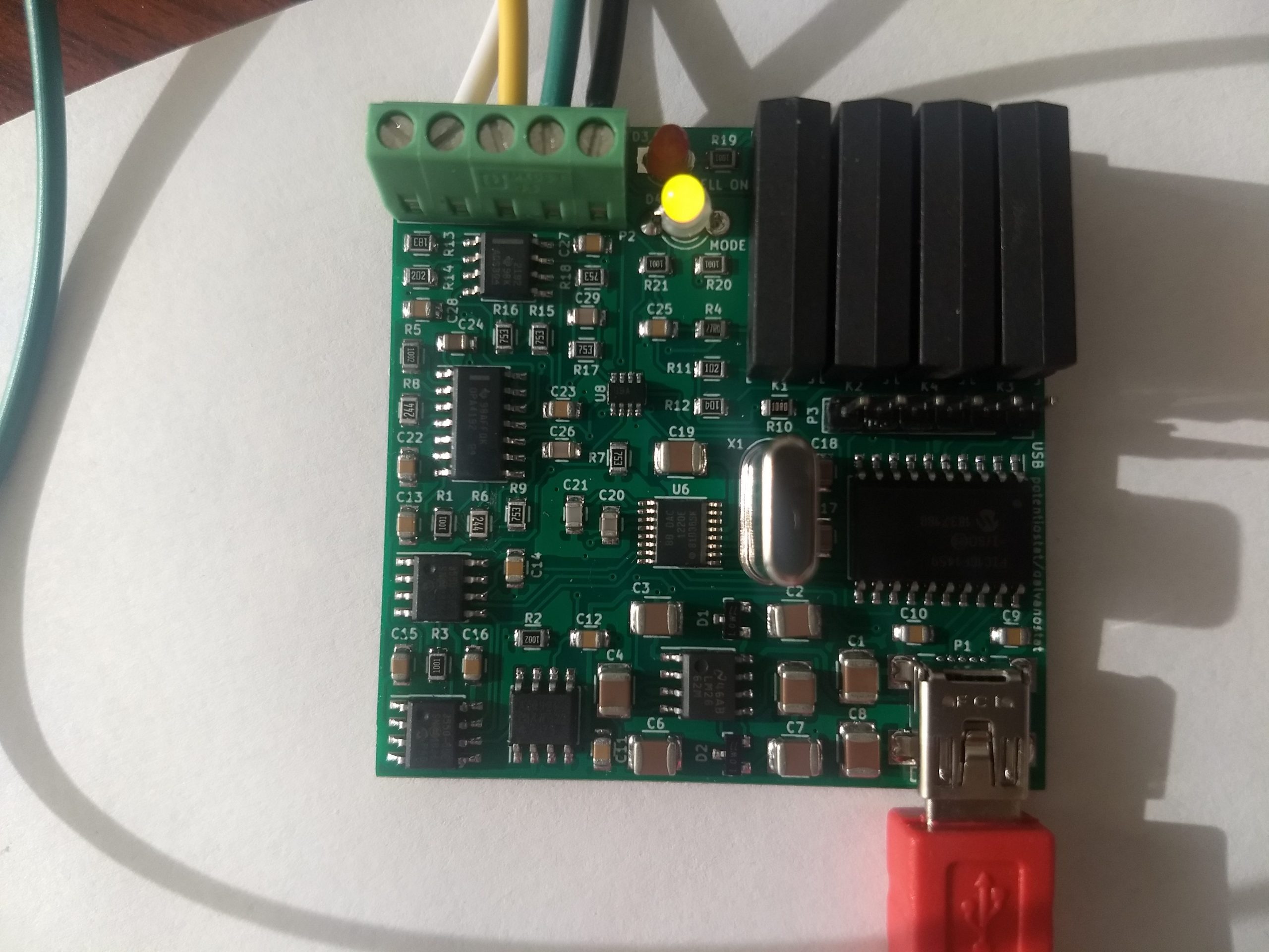
This is the Chinese made potentiostat-galvanostat board built by PCBway using the files I provided (which are files obtained/modified from the paper mentioned before).
If you have read my last few posts, this is exactly what happened, I completely failed at successfully assembling this board myself (not the best soldering hand in town!) but thankfully received my fully assembled PCB from China a couple of days ago. The PCB from china worked flawlessly, allowing me to perform the calibration and have a fully functioning potentiostat/galvanostat for home use.
The python software provided by the creators of this potentiostat also worked really well. Using the knowledge I obtained within the last couple of posts, I was able to easily use the drivers provided by the authors to use this software without any issues. The software implements some basic experiments, like CV, charge/discharge curves and Rate testing, but the best thing is that the entire thing is open source, allowing me to customize the experiments to do whatever I want, something I know many researchers wish they could do with the expensive software packages – all closed source – provided by normal potetionstat manufacturers.
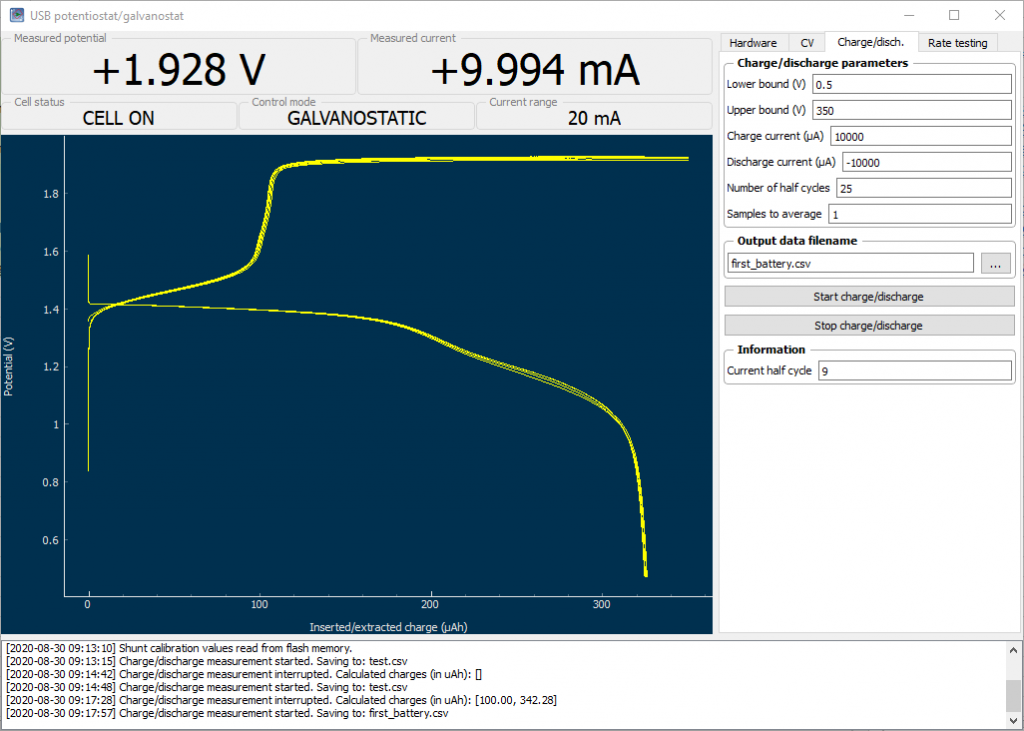
These are some charge/discharge curves I am now measuring for a prototytpe battery I made. I modified the software in order to be able to do the charge to 350 uAh, then proceed with the discharge.
This ends my quest for the building of a – now not so much – DIY potentiostat/galvanostat, giving me the functionality of a piece of equipment that usually costs around 1000-3000 USD for just a couple of hundred dollars. Even more, this potentiostat allows me to use current in the -25 to 25 mA range, something that isn’t that common unless you go for the more expensive potentiostats above the 3K+ USD range, since the cheapest potentiostats are usually built for high sensitivity at lower currents – because these are mostly intended for analytical chemistry experiments – rather than for the charging/discharging of battery cells.
My posts will now move onto the experimental batteries I am attempting to build and their characterization. I have always noticed that DIY batteries on the internet are almost never properly characterized – no wonder given how difficult it has been up until now to get access to proper equipment to do so – but with this piece of hardware I will now be able to perform all of these experiments without issues.
With some improved soldering skills I reattempted soldering of all the components into the brand new PCB I had left from Osha Park. After doing this I still experienced a significant amount of shorts but this time I was able to pinpoint the sources by some smoke coming off the PCB (not the greatest sign!). In the end all the shorts were coming from what seems to be the underside of the microchips, probably related with some flux residue that got carbonized and became somewhat conductive after the chips were soldered and the circuit was powered.
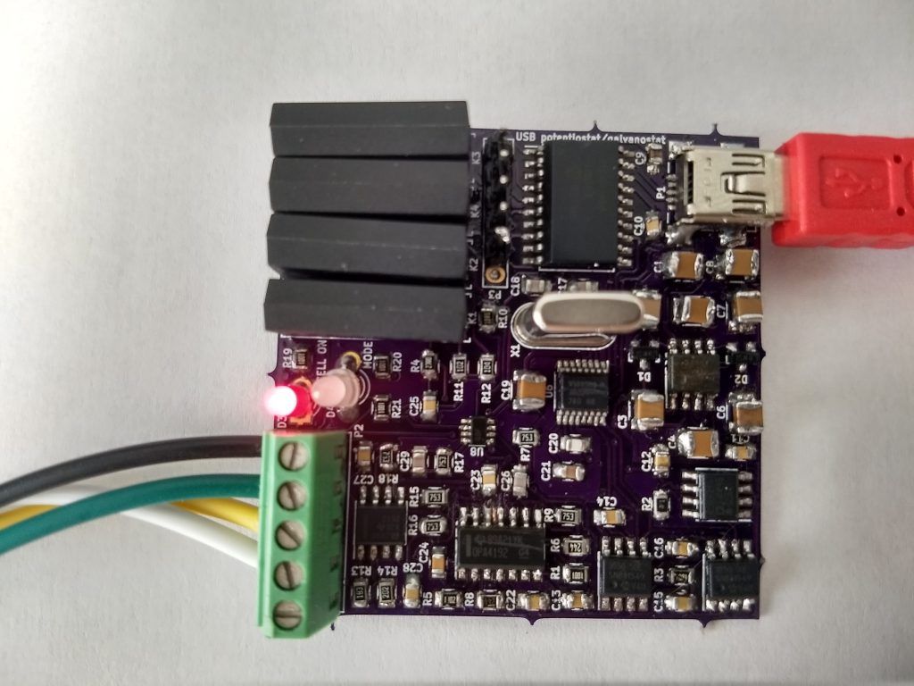
My somewhat successfully powered DIY potentiostat/galvanostat
With this information I now resoldered all the chips, being very careful about cleaning all the flux to ensure that there were not shorts after the chip was put into place. With all these shorts removed I was able to finally power the board without any excessive current drain.
Due to the fact that the drivers that come with this device are unsigned I had to restart windows using the “Advanced boot options” to ensure that driver signing was disabled. Also remember to install pyusb and usblib before launching the python program.
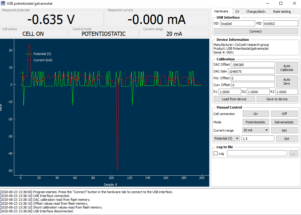
With this done I was able to successfully connect the PCB to the computer and use the software to interact with it. However after trying to do the calibration I noticed that the entire potentiostat/galvanostat functionality was actually not working and I was actually unable to set any potential without the circuit going a bit “crazy”. As you can see in the image below, everytime I tried to set the potential to some value I just got some random potential being set, with current bouncing all over the place.
Trying to set the potential of the device to 1.5V with RE connected to WE and CE connected to SE just generated a bunch of noise
Feeling the temperature of the different chips, the one that is overheating seems to be the OPA4192 chip. I tried to remove it and resolder it again, but I have the same problems and the same type of abnormal behavior. Right now it seems that the most likely scenario is that all my desoldering and soldering endeavors have fried one of the components of the board, meaning that I might not be able to get it to work at all with the current components.
Thankfully plan B is still going on – a PCB being fully assembled by pcbway – so I should be able to get a fully working board within the next couple of weeks. I am still debating whether it’s worth it to order new components and try on a new board – with my already gained experienced – but I think I’ll wait for the working PCB to ensure this board works as I expect it to before I make any further DIY attempts.
As I explained on my last post, I want to build a system to characterize batteries at a small scale at my home. This means being able to test things like their coulombic efficiency and measure things like charge/discharge curves. The perfect solution came as the USB potentiostat/galvanostat published in this paper so I order 3 boards using Oshapark and got the rest of the parts from microchipdirect and digikey.
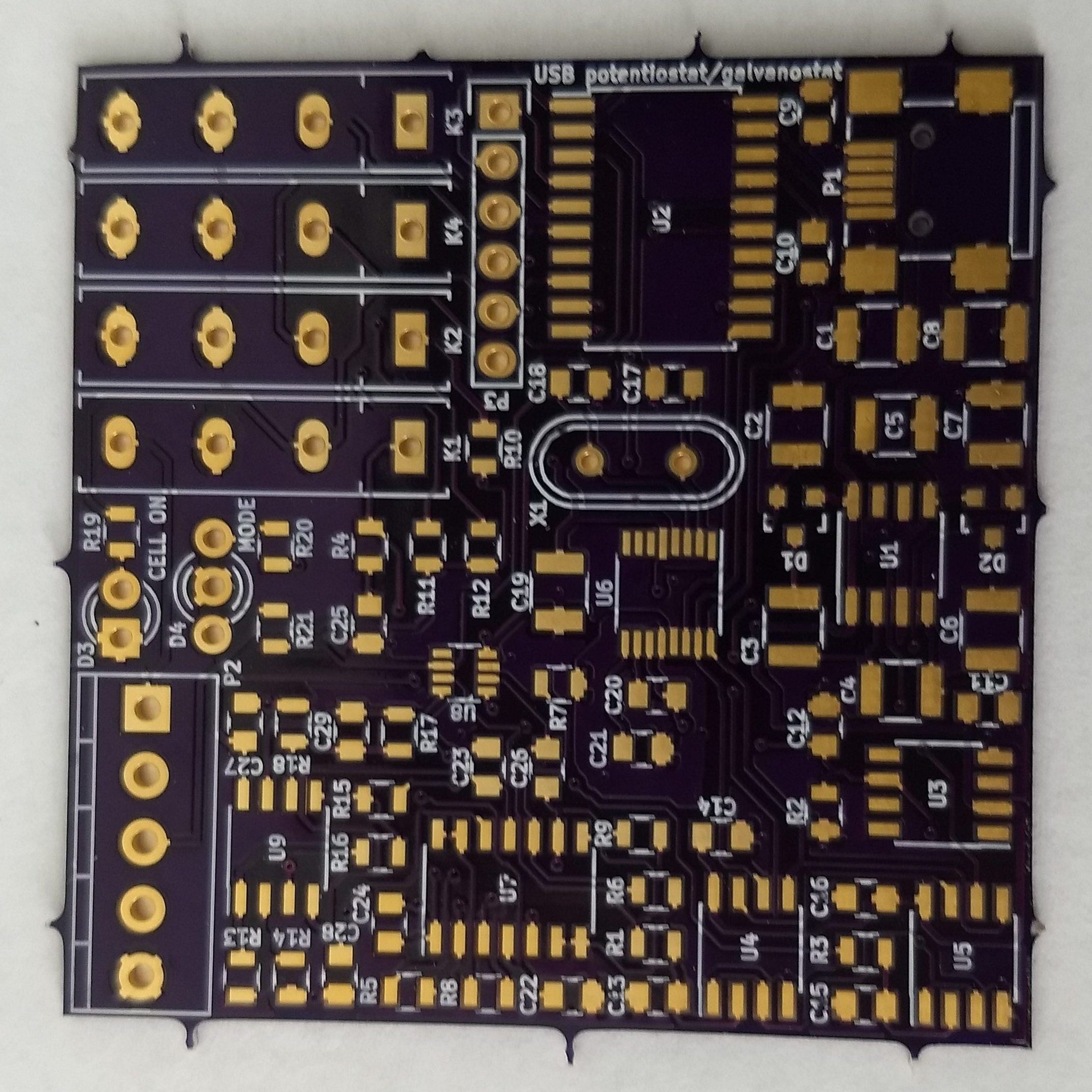
PCB board I received from Oshapark
I received my PCB order last week – as shown above – and proceeded to solder the components that I received as well. After soldering all the components I then connected the board to the PicKit3 programmer using the programming leads. By the way, the square pin right below the K3 mark should match pin 1 in the programmer, something that is not mentioned within the above cited paper.
When I did this I used the MPLAB X IPE v5.4 software, downloaded from this link. Using the advanced options I made the PicKit3 provide power to the board and I then proceeded to program it at 4V because when I connected it at 5V I received some erros about VDD not matching between the microcontroller voltage and the provided voltage. In the end I was able to program and verify the chip at this voltage with the hex file provided by the authors of the paper.
After this I then connected the chip into the computer using a USB port and instantly received a USB overcurrent warning, which immediately disconnected the PCB from my computer (uh oh). After checking the board I noticed a short after the charge pumping circuit, where the +9V line was almost shorted to ground, with a resistance of around 10-100 ohm when it should be at least 10kohm given the lowest resistance connected between ground and this line (R2). You can test this by measuring resistance between the leads in R2.
After painfully taking out all the components one-by-one from one PCB and soldering them onto a second one I realized that my problem was that overheating the PCB actually created a short-to-ground in this line, more likely than not related with partial melting of the PCB in the U8 microchip leads where the +9V and ground lines are particularly close to one another. This can actually happen by heating anywhere on the board that’s connected to the ground line, even if you overheat something like the LED D3 or D4 lines. I noticed because I caused the same damage on the second board I was working on, even though the lines were not shorted right before I was working on the D4 LED but became shorted right after I spent around 20 seconds applying heat (yes, my bad).
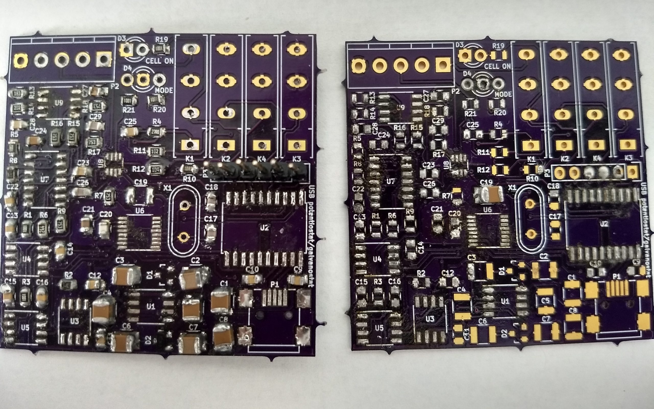
Two boards I worked on that are now useless. Left one was the first I soldered all components on, second is the one I was testing components on when I noticed the short caused by over-heating the ground line.
Right now I sadly only have one board left (sigh) and have already desoldered and soldered a lot of the components. I now need to desolder all the remaining components from these two boards solder them onto the third board, although this case I will need to be especially careful about how I apply heat to the board as I definitely do not want to cause this shorting issue again. I will update this blog after I try again.