As I explained on my last post, I want to build a system to characterize batteries at a small scale at my home. This means being able to test things like their coulombic efficiency and measure things like charge/discharge curves. The perfect solution came as the USB potentiostat/galvanostat published in this paper so I order 3 boards using Oshapark and got the rest of the parts from microchipdirect and digikey.
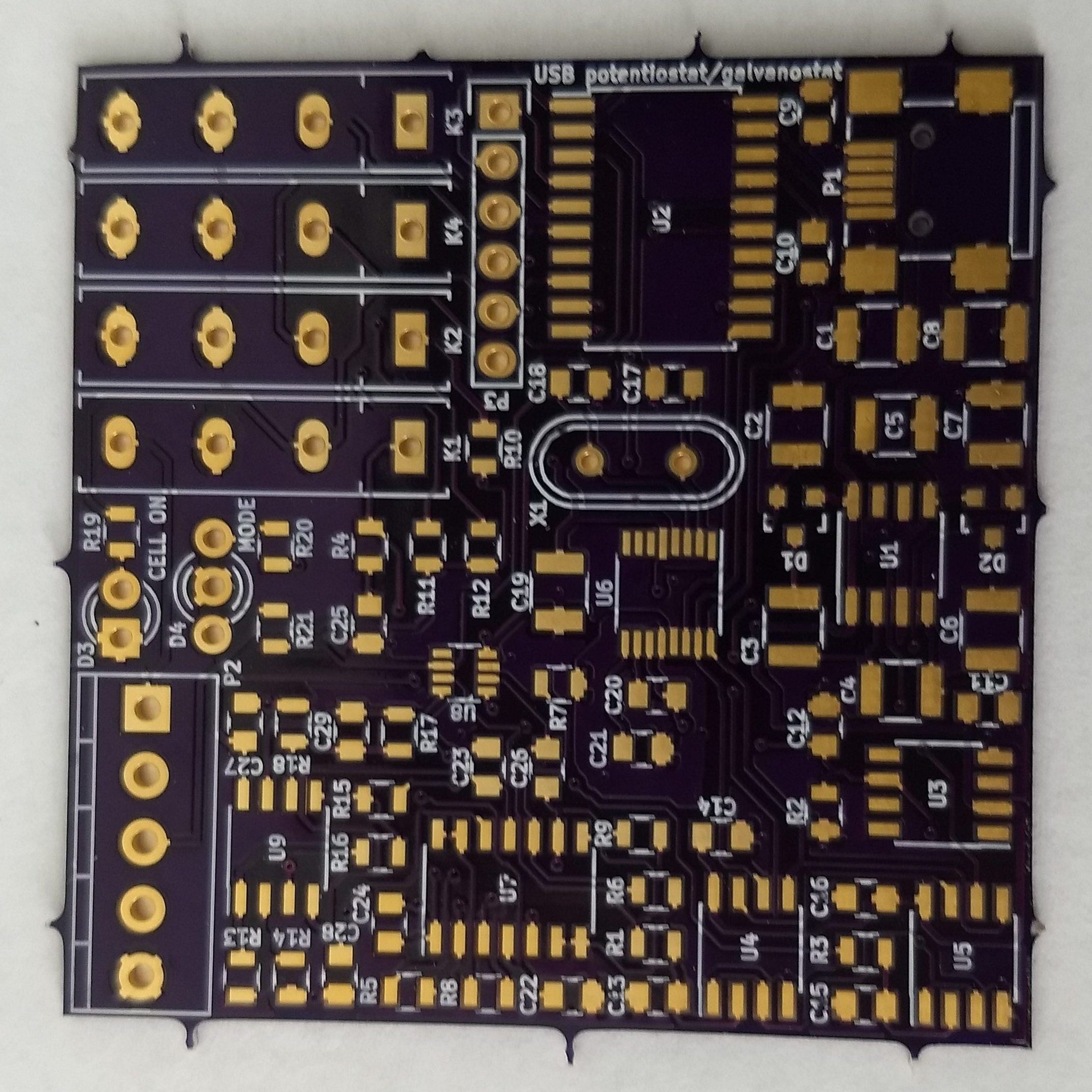
I received my PCB order last week – as shown above – and proceeded to solder the components that I received as well. After soldering all the components I then connected the board to the PicKit3 programmer using the programming leads. By the way, the square pin right below the K3 mark should match pin 1 in the programmer, something that is not mentioned within the above cited paper.
When I did this I used the MPLAB X IPE v5.4 software, downloaded from this link. Using the advanced options I made the PicKit3 provide power to the board and I then proceeded to program it at 4V because when I connected it at 5V I received some erros about VDD not matching between the microcontroller voltage and the provided voltage. In the end I was able to program and verify the chip at this voltage with the hex file provided by the authors of the paper.
After this I then connected the chip into the computer using a USB port and instantly received a USB overcurrent warning, which immediately disconnected the PCB from my computer (uh oh). After checking the board I noticed a short after the charge pumping circuit, where the +9V line was almost shorted to ground, with a resistance of around 10-100 ohm when it should be at least 10kohm given the lowest resistance connected between ground and this line (R2). You can test this by measuring resistance between the leads in R2.
After painfully taking out all the components one-by-one from one PCB and soldering them onto a second one I realized that my problem was that overheating the PCB actually created a short-to-ground in this line, more likely than not related with partial melting of the PCB in the U8 microchip leads where the +9V and ground lines are particularly close to one another. This can actually happen by heating anywhere on the board that’s connected to the ground line, even if you overheat something like the LED D3 or D4 lines. I noticed because I caused the same damage on the second board I was working on, even though the lines were not shorted right before I was working on the D4 LED but became shorted right after I spent around 20 seconds applying heat (yes, my bad).
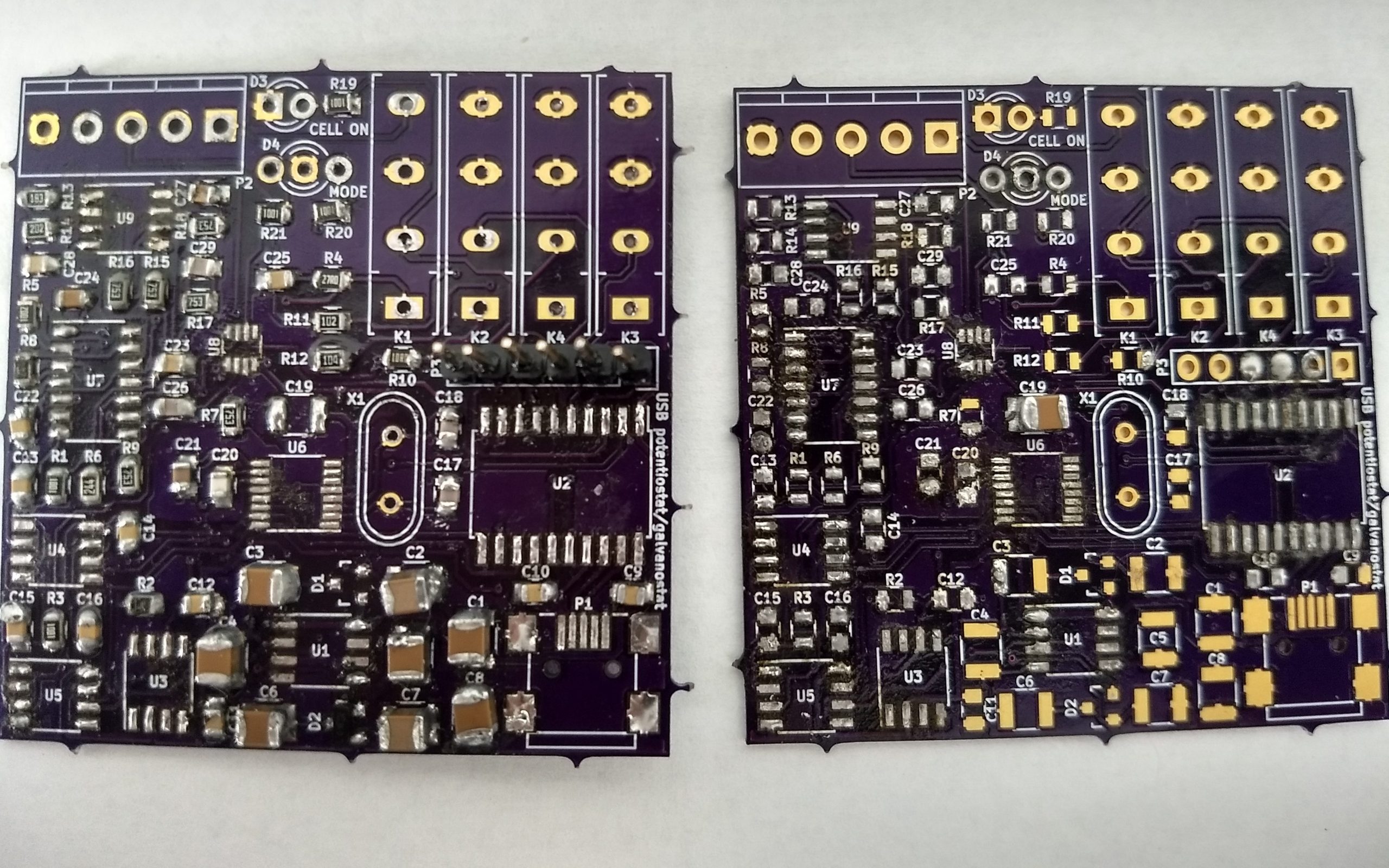
Right now I sadly only have one board left (sigh) and have already desoldered and soldered a lot of the components. I now need to desolder all the remaining components from these two boards solder them onto the third board, although this case I will need to be especially careful about how I apply heat to the board as I definitely do not want to cause this shorting issue again. I will update this blog after I try again.