With some improved soldering skills I reattempted soldering of all the components into the brand new PCB I had left from Osha Park. After doing this I still experienced a significant amount of shorts but this time I was able to pinpoint the sources by some smoke coming off the PCB (not the greatest sign!). In the end all the shorts were coming from what seems to be the underside of the microchips, probably related with some flux residue that got carbonized and became somewhat conductive after the chips were soldered and the circuit was powered.
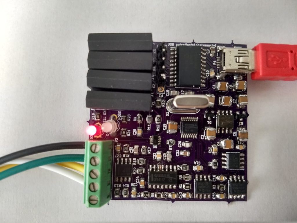
With this information I now resoldered all the chips, being very careful about cleaning all the flux to ensure that there were not shorts after the chip was put into place. With all these shorts removed I was able to finally power the board without any excessive current drain.
Due to the fact that the drivers that come with this device are unsigned I had to restart windows using the “Advanced boot options” to ensure that driver signing was disabled. Also remember to install pyusb and usblib before launching the python program.
With this done I was able to successfully connect the PCB to the computer and use the software to interact with it. However after trying to do the calibration I noticed that the entire potentiostat/galvanostat functionality was actually not working and I was actually unable to set any potential without the circuit going a bit “crazy”. As you can see in the image below, everytime I tried to set the potential to some value I just got some random potential being set, with current bouncing all over the place.
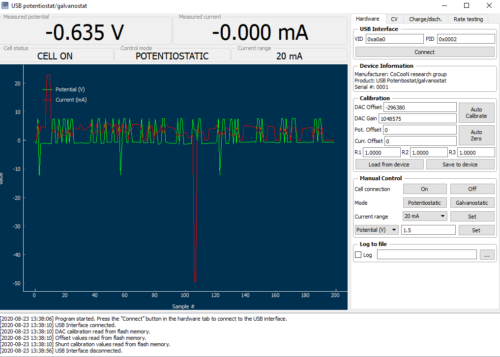
Feeling the temperature of the different chips, the one that is overheating seems to be the OPA4192 chip. I tried to remove it and resolder it again, but I have the same problems and the same type of abnormal behavior. Right now it seems that the most likely scenario is that all my desoldering and soldering endeavors have fried one of the components of the board, meaning that I might not be able to get it to work at all with the current components.
Thankfully plan B is still going on – a PCB being fully assembled by pcbway – so I should be able to get a fully working board within the next couple of weeks. I am still debating whether it’s worth it to order new components and try on a new board – with my already gained experienced – but I think I’ll wait for the working PCB to ensure this board works as I expect it to before I make any further DIY attempts.