To build an Fe/Mn flow battery we need a cation exchange membrane to separate the catholyte and anolyte chambers of the device. In this post I want to talk about my initial thoughts about how to create a DIY membrane for this purpose.
Commercial cation exchange membranes do exist. Nafion membranes are the most commonly used, but their cost is too high. Just a small 10cm x 10cm square of Nafion can cost upwards of 50 USD, depending on the type of Nafion used. Lower cost membranes (like SPEEK based membranes) have been tested in the literature, but I cannot find any place that actually sells these “lower cost” membranes at a truly lower cost than Nafion.
To be able to make a viable DIY flow battery we need a membrane that we can make, that is lower cost. The requirements of a cation exchange membrane for the Fe/Mn system would be as follows:
- Not dissolve in water at neutral pH.
- Made from readily available, low cost materials.
- Mechanically stable.
- No reaction with any of the redox species in solution.
- Contain anionic groups (which makes it selective to cations)
- Have high conductivity
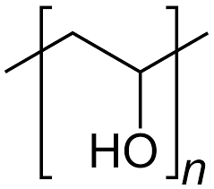
I looked at potential materials to build this membrane and PVA has become the most prominent base material. It is a polymer with OH functional groups, which I can use to react with readily available chemicals to create a functionalized polymer. My first experiments will involve using phosphoric acid, urea and potassium silicate to create functionalized membranes.
I will prepare 10% w/w solutions of PVA in distilled water, then add different amounts of the above mentioned additives to determine which compositions cast best and have the best properties. I will be casting the films in petri dishes, as this seems to be the most common method in the PVA membrane literature. I will also possibly anneal the membranes by heating them at different temperatures after they have settled.
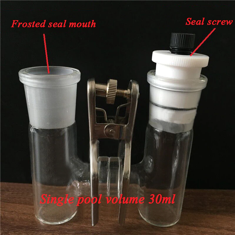
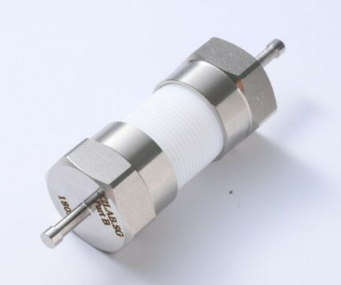
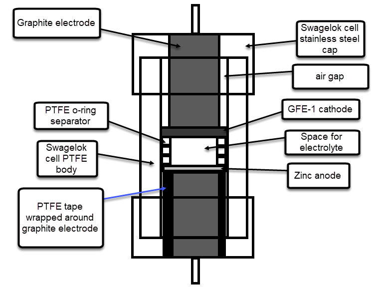
I have also bought a double chamber electrochemical cell to perform experiments using these membranes. The idea is to measure if there is any crossover across the membranes and possibly also measure the ionic conductivity of the membrane.
To measure crossover of ions I can setup one side with the Fe salt and another with the Mn salt, then carry out cyclic voltammetry measurements on the Mn side as a function of time, to measure the appearance of the Fe peak (if there is any crossover). I can compare times between membranes as well. I can also test microporous membranes and non-functionalized PVA membranes, to obtain some baseline measurements. If I setup one side with just NaCl and the other with Fe, I can likely obtain more sensitive measurements (as I will have no current from reactions with Mn species).
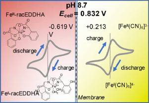
Additionally if I use Fe-EDDHA I could sample the solution and measure the appearance of the Fe-EDDHA visible absorption peak near 500nm, which is highly sensitive given the chelate’s very high molar extinction coefficient. Although for this I would near to purchase a Uv-Vis spectrometer, which would cost me 500-1000 USD.
I can also measure ion diffusion by setting up distilled water on one side and a 3M NaCl on the other side and measuring conductivity as a function of time on the distilled water side. This will allow me to compare different membranes and see which ones transport ions faster. If I add Fe chelate to the NaCl I could perhaps measure both ion transport and selectivity simultaneously.
It will be a very interesting journey!