I’ve done a lot of experiments during the last two years around the construction of Zinc halide batteries, in particular, Zn-Br and Zn-I batteries. So far, I have been unable to find a battery setup that provides high energy and coulombic efficiencies, high capacity and high stability.
Zinc-Bromine batteries suffers from problems related with Br2 diffusion, zinc dendrites, hydrogen evolution and other problems that arise when you try to resolve these issues. Trying to add complexing agents, increase electrode distance or add physical barriers, will often increase coulombic efficiency at the expense of energy efficiency, such that batteries with low self-discharge or high capacity will tend to have extremely low energy efficiency values (often below 20%). Having a battery where you need to put 20kWh in to take 2kWh out is just not a viable strategy for most people. Hydrogen evolution reactions are also inevitable with Zn-Br batteries, and these irreversibly destroy the electrolyte as a function of time.
Zn-Br batteries might be easy to show in online videos and tout as a great chemistry with lots of possibilities, but the reality of constructing a >60Wh/L static Zn-Br battery with a long cycle life shows that this is extremely hard to achieve. This is why you will find no one showing proper testing – charge/discharge curves with CE and EE numbers for many cycles – of such DIY static batteries. You can read other posts in my blog and this forum thread, for more information about my journey in Zn-Br batteries.
The above were the reasons why – after doing a lot of experiments to get to know these batteries quantitatively – I decided to move to the Zinc-Iodine chemistry.
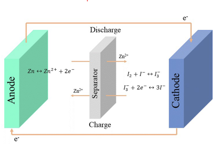
Zinc-Iodine batteries do not suffer from hydrogen evolution issues – due to the lower potential needed to charge the battery – but they also have strong problems dealing with I2 migration, especially due to the very iodide rich electrolyte, which generated a lot of readily soluble triiodide (I3–). Although many solutions to these problems have been tried and published in peer reviewed journals, most are extremely hard to apply in practice and out of reach for someone with limited equipment and resources.
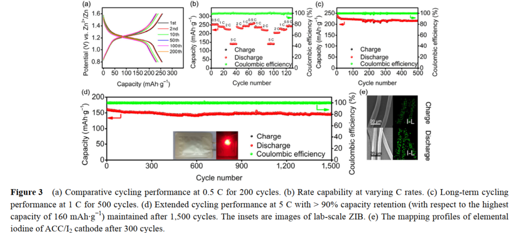
However, there is some hope. A paper published in 2019 got around the problem of the triiodide ion by using a “water in salt” approach (WiS). That is, they create a very highly concentrated solution of zinc chloride and potassium iodide, where water is a very minor component by mass. In this case, they add around 2g of ZnCl2 and 0.8g of KI to only 1mL of distilled water. In such a concentrated salt solution, iodide prefers to bond to Zn to form complexes, as the formation of the triiodide ions is strongly disfavored by the environment. This is proven extensively in the paper by the use of Raman spectroscopy, supported by computational chemistry calculations.
Thankfully, both ZnCl2 and KI are readily available chemicals plus, the electrode and separator material used by the researchers are also easy to get. The cathode is made out of carbon paper, the anode is zinc metal and the separator is cellulose filter paper. I purchased the salts for around 4 USD/kg (ZnCl2) and 40 USD/kg (KI).
Note that ZnCl2 is extremely hygroscopic, so it needs to be kept under airtight conditions. Solutions of ZnCl2 are also extremely acidic (pH < 1) so you need to be very careful when handling ZnCl2 solutions that are this concentrated. Zinc chloride also heats solutions aggressively when dissolved.
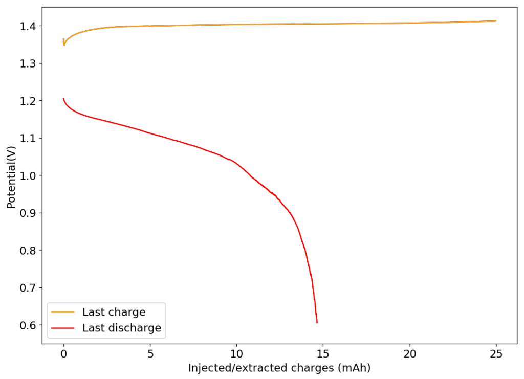
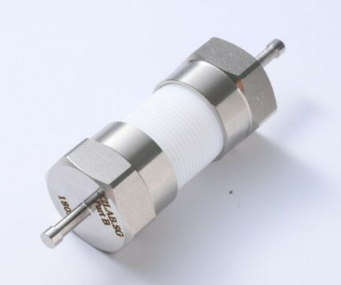
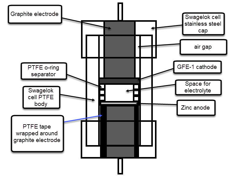
The results of trying to reproduce their research were quite astonishing. I prepared the electrolyte as published and used my Swagelok cell for testing. I used a Whatman 42 filter paper as separator and an HCB-1071 carbon cloth as cathode (note the variety kit has the 15mil, which is the one I used). For the anode, I used the surface of the graphite electrode of my Swagelok cell. In total, the thickness of my battery was just 350 microns (0.0350cm).
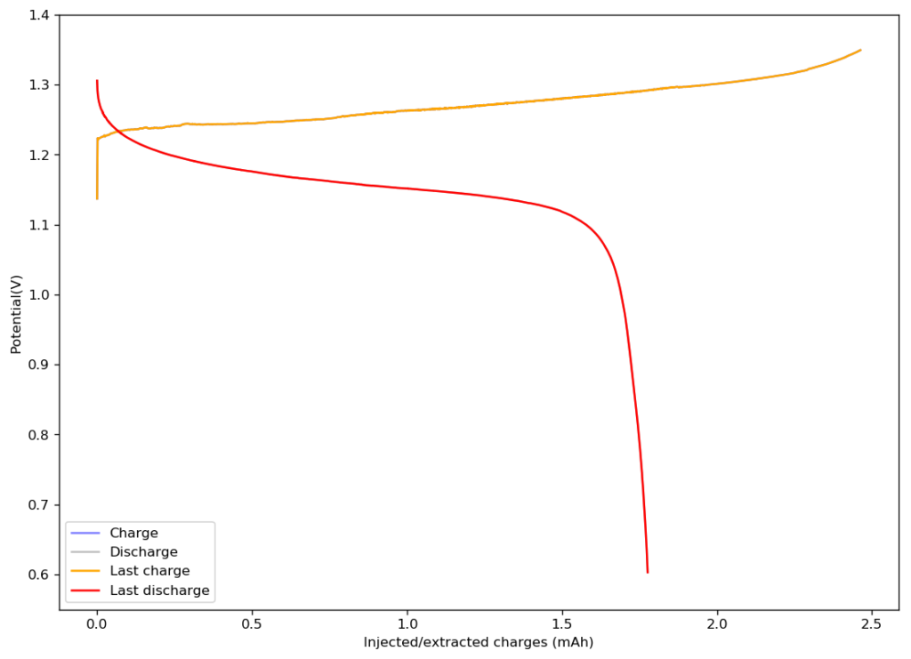
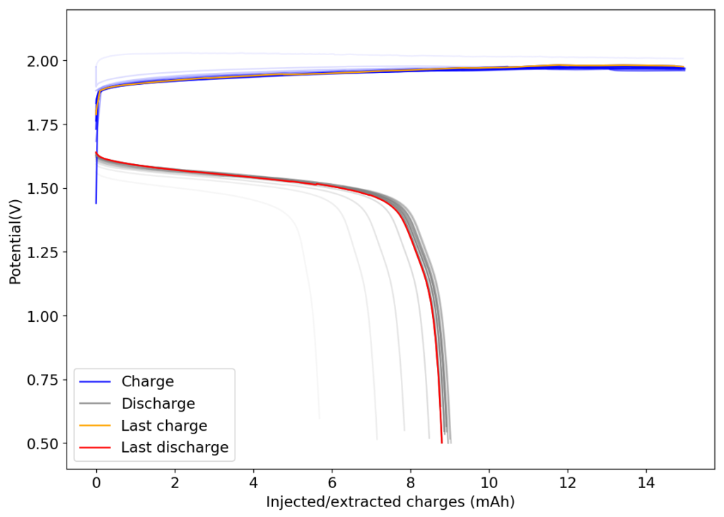
The above image shows you the results from the first charge/discharge cycle of this device. The capacity in this first cycle was 1.77mAh. Given the volume of this battery, the energy density is currently at 58Wh/L, the best energy density I have been able to create for any device.
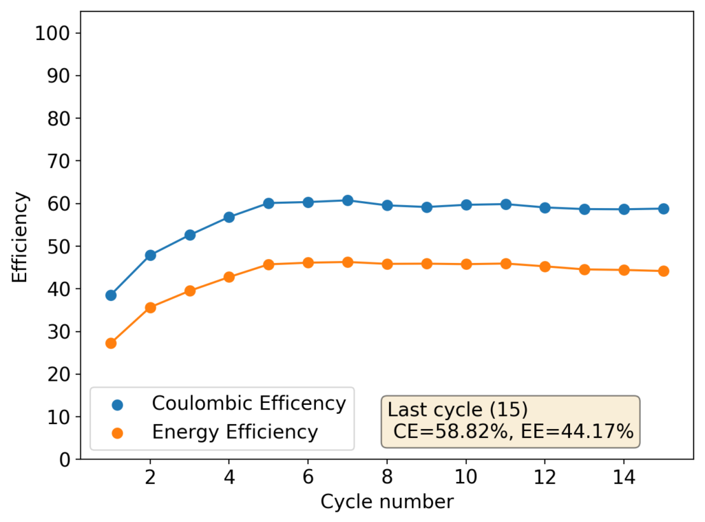
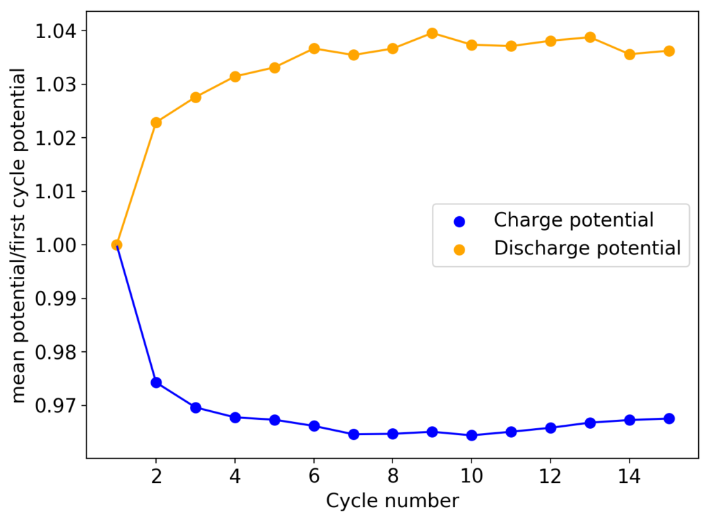
I am now going to study the cycling characteristics of these devices further. I want to determine how the CE and EE change as a function of time and how the capacity changes as well. Taking this device apart confirms that elemental iodine is deposited on the carbon cloth and no appreciable triiodide – which has an orange color – is formed. This is also confirmed by the massive jump in CE and EE in these devices.
The above chemistry finally points to a path for a DIY battery that can be easy to build with readily available chemicals and materials. My hope is that this can lead to practical capacities in the >50Wh/L, with reasonable costs and hopefully low self-discharge and a long cycle life.