For the past week I have been trying to find the reason why the internal resistance of my batteries seems to be increasing linearly as a function of the cycle number. I sought to evaluate several different hypothesis, starting with the potential deterioration of the graphite cathode as a cause for this. Using titanium as a cathode generated similar results though plus a substantial deterioration of the cathode as a function of time. The graph below shows you a Titanium cathode and how it was pitted aggressively by the oxidative conditions of the cathode side of the battery.
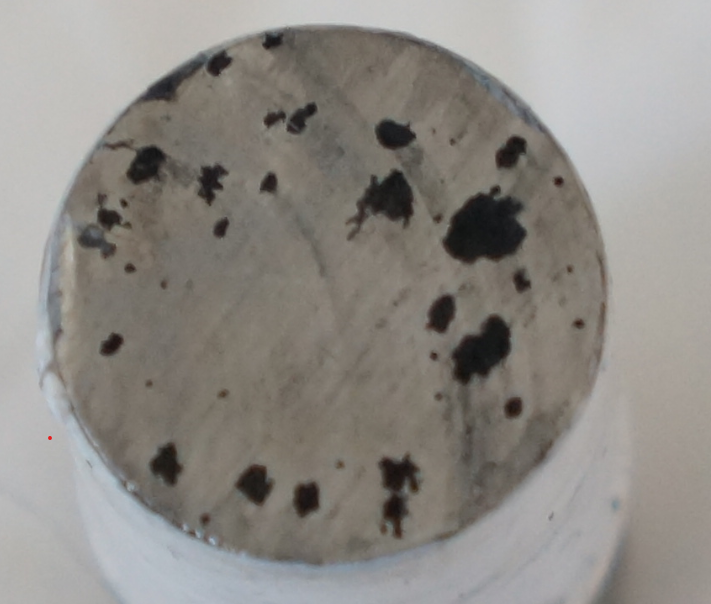
The above results showed that deterioration of the graphite cathode was not the main cause of the increase in internal resistance, plus, it also showed that titanium – at least in this form – is not a suitable replacement for the graphite electrode in the Swagelok cell.
One interesting thing about the internal resistance problem was that opening up the cell, taking out the anode and putting the anode back in, seemed to regenerate the device to close to its initial conditions. This pointed to the process that was causing the deterioration to be somewhat reversible, at least in that it depended on the state of the device and was therefore likely not caused by the deposition of some insoluble film in the cathode or the unwanted precipitation of something within the electrolyte.
Thinking about this, I realized that a significant amount of hydrogen was being generated inside the battery at these potentials, which, given the flat anode geometry, was unable to escape the device. This trapped H2 gas, against the anode created zones of high resistance which accumulated with time up to the point where they basically prevented the electrode from working correctly at all.
To test this hypothesis I assembled an inverted geometry cell with a GFE-1 cathode treated with 10% TMPhABr on top and a graphite anode at the bottom. The cell used no solid separator, but a spacer made from 3 PTFE o-rings. Sadly I was running out of ZnBr2 and made a mistake in the solution preparation as well, so the electrolyte used is quite strange with a concentration of 1.5M ZnBr2 + 5% PEG-200 + 5% Tween 20. I meant to prepare 0.5% but made a mistake in my calculations.
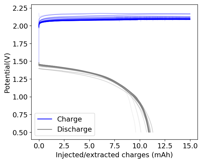
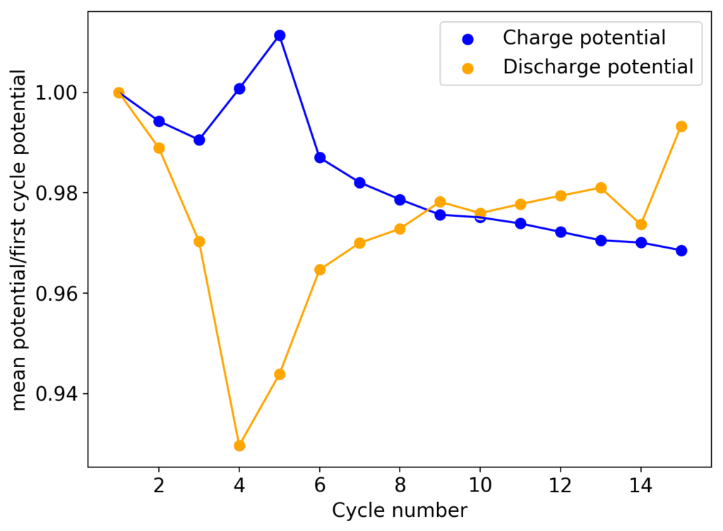
As you can see in the curves above, an inverted device appears to behave in a completely opposite way to my previous devices with larger cycle numbers. The charge and discharge potentials seem to be evolving favorably as a function of time, with the charge potential decreasing and the discharge potential increasing. This means that the internal resistance of the device is actually becoming lower and lower as time goes on. The hydrogen gas is no longer a problem since, as a low density gas, it will tend to go up the cell, into the electrolyte and cathode, where it reacts with perbromides or elemental bromine in solution which regenerates the chemistry (as the hydrobromic acid formed then diffuses and reacts with any ZnO formed in the anode).
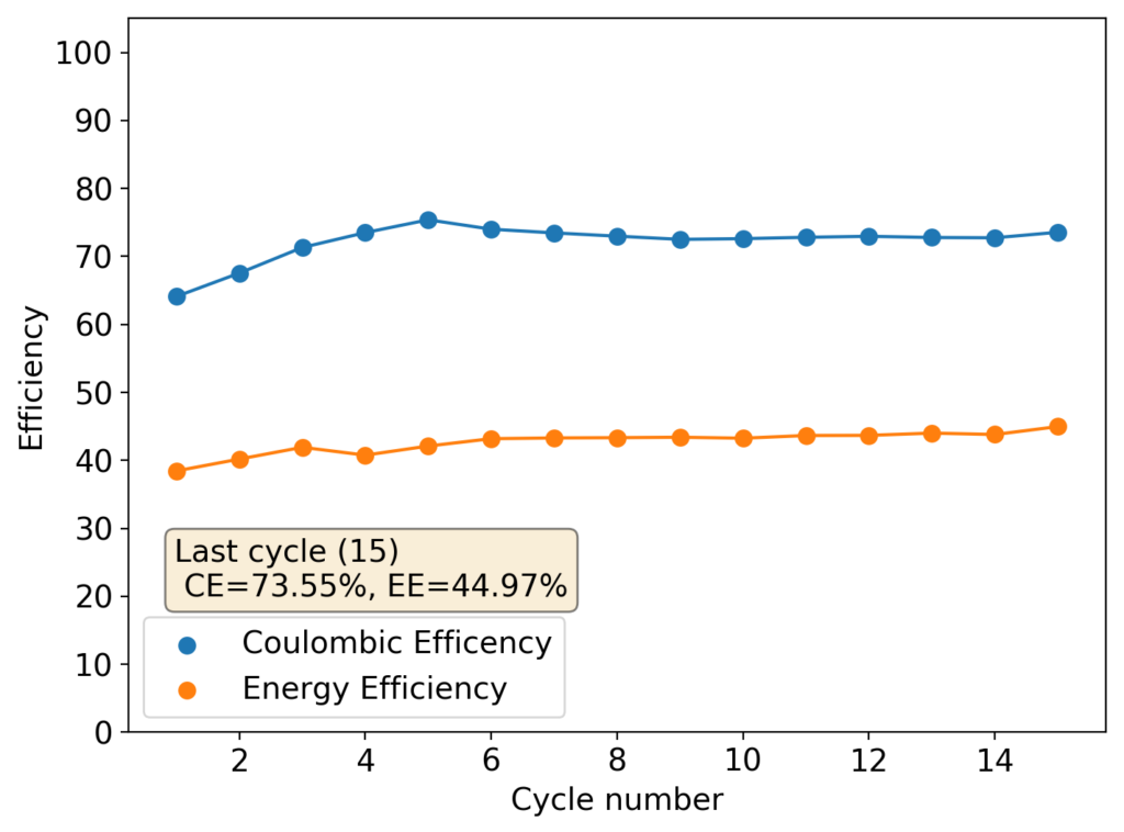
The Coulombic and Energy efficiencies of this device are quite low though, which is likely a consequence of the bigger amount of PEG-200 and Tween-20 used, plus a lower concentration of ZnBr2. I will be reproducing this setup with a freshly and properly prepared electrolyte as soon as I get new ZnBr2 this week but I thought these results were interesting enough to share with you. I will also continue cycling the above device to see if it eventually fails due to dendrites or some other reason.