Zinc Bromine Batteries: Why propylene carbonate will not work as a cathode electrolyte

I have written several blog posts in the past about the potential use of propylene carbonate (PC) as a potential non-aqueous solvent in Zn-Br batteries. However, through my research I have now discovered that this solvent will not work in these devices as a cathode electrolyte, due to the way it interacts with the chemicals that are generated within the cell. In this post I will explain to you the experiments I did and why I reached this conclusion.

The idea with using PC was initially to completely replace the electrolyte within the cell. This was discarded right away due to ZnBr2 solubility issues and low conductivity issues of the constructed cells. The idea then evolved to using a tetrabutylammonium bromide (TBABr) saturated PC solution (PC-TBABr) as an organic layer in an inverted device, since this layer can rest on top of a Zn-Br solution and can even remain on top after mixing if the Zn-Br solution is concentrated enough (>4M).

Small cell I used to visually study what happened with a PC-TBABr containing device. The cell was not characterized as the geometry is not reproducible and the surface area is too big for my testing equipment.

The organic layer is completely immiscible with the highly concentrated ZnBr2 layer and it was my hope that the TBABr3 produced in the cathode would be substantially more soluble in the PC-TBABr compared to the aqueous phase. Given that the PC phase is more than 50% TBABr, it seemed very likely that the produced perbromide would have a significantly higher affinity for the PC-TBABr.

To confirm whether this was happening, I constructed an inverted cell using a glass vial in order to be able to see what was going on (which you can see above). I placed a zinc anode at the bottom, used fiberglass as a separator and placed a GFE-1 cathode saturated with PC-TBABr on top using some C4 carbon cloth as a current collector. Before placing the GFE-1 cathode I filled the cell with a 4.2M ZnBr2 electrolyte, which makes the PC-TBABr remain less dense even after prolonged mixing. Since my objective was not to measure efficiencies with this device, but just to observe the chemical processes, I did not strive for a reproducible geometry.

After charging for a while with 3 charged AA batteries at more than 3V – just to make the process go fast – I noticed a lot of TBABr3 forming and precipitating within the cell. Sadly, the perbromide seems to form on the cathode and then immediately migrate out and into the aqueous phase. To my absolute surprise, the TBABr3 – which is more of a liquid rather than a solid – has higher affinity for the aqueous phase, although it doesn’t solubilize within it but rather forms a suspension with it.

I then proceeded to take the electrolyte out of the cell and perform an extraction using some additional PC-TBABr and surprisingly, all the perbromide stays in the aqueous phase after mixing and just refuses to get into the PC-TBABr. For this reason, PC is not going to work as a cathode electrolyte within the device, as the perbromide just exits it and never returns. This is probably why my devices trying to do this never seemed to work for too long.

Zinc Bromine Batteries: Preparing a solution of known Zinc Bromide concentration using Sodium Bromide and Zinc Sulfate

I wrote a post a while ago about how to prepare solid Zinc Bromide from Zinc Sulfate and Sodium Bromide through the use of water and isopropyl alcohol. However, this method has substantial issues when it comes to its practical implementation, as taking ZnBr2 out of solution is an arduous process that can also be dangerous due to the often aggressive splashing of hot concentrated ZnBr2 solutions. Taking the Zinc Bromide to a solid also seems unnecessary given that in the end we want to end up with ZnBr2 solution for batteries. What if we could just mix Zinc Sulfate and Sodium Bromide and somehow end up with a solution known Zinc Bromide concentration after precipitating the Sodium Sulfate? I will tell you how to do just that in this post.

Result of the process after cooling in the freezer for a couple of hours. An abundant sodium sulfate precipitate is forming.

The solubility of Zinc Bromide is exponentially greater than that of Zinc Sulfate, Sodium Bromide and Sodium Sulfate so mixing a solution of Sodium Bromide and Zinc Sulfate generates a concentrated solution of Zinc Bromide and precipitates almost everything else. At 0C the solubility of ZnBr2 is still 311g/100mL while that of Na2SO4 drops to 4.76g/100mL and that of ZnSO4 drops to nearly 0. It is important to keep an excess of Zinc Sulfate in the reaction though as the solubility of NaBr is still quite high at 0C, reaching more than 79g/100mL.

In order to carry out this synthesis I have followed this process:

  1. In a 250mL clean beaker, weight 45g of Zinc Sulfate Monohydrate
  2. Add 51g of Sodium Bromide
  3. Add 100mL of distilled water (it’s important to use distilled water)
  4. Heat the mixture with stirring till boiling starts or everything dissolves.
  5. Let the mixture cool until it reaches room temperature
  6. Optionally you can add 10mL of isopropanol here, which greatly reduces the Sodium Sulfate contamination. (rubbing alcohol works just fine)
  7. Place in a freezer for 24 hours.
  8. Filter the solution to remove all Sodium Sulfate and unreacted Zinc Sulfate.
  9. If isopropanol was added, boil the solution until all the alcohol is removed.

What you are left with is a concentrated solution of ZnBr2 of unknown concentration. Since we do not know how much the volume of the solution changed due to the reaction and some volume of solution is always left wetting the remaining solid, we cannot accurately determine the molarity of the solution from the things we added and what we obtained. We need to perform some measurements to get an idea about how much ZnBr2 we have in solution.

Density of a Zinc Bromide solution as a function of its molar concentration.

However, since this is a mostly ZnBr2 containing solution – with likely less than 5% of the salt weight being from sodium sulfate contamination – we can estimate the amount of Zinc Bromide by measuring the density of the solution and looking at experimental results showing the density variations of pure Zinc Bromide solutions. Using the experimental data from this paper from 1994, I was able to create the above graph, which allows you estimate how concentrated your Zinc Bromide solution is. Note that you should input the density in the equation expressed in kg/m^3.

In order to measure the density of the solution, I used a 10mL pycnometer, which you can buy here for a low price. A pycnometer allows you to very accurately determine the density of a solution since its volume is exact. By weighting the empty pycnometer and the filled pycnometer and then dividing the difference of this weights by 10 (volume of the pycnometer), you can obtain the measurement in g/mL which you can multiply by 1000 to get the value in kg/m^3.

Once you know the approximate concentration of your solution you will know how much you would need to dilute the solution to arrive at your desired concentration. Solutions produced with the above method are bound to be in the 4-7M region, so you will probably need to dilute them to arrive at a concentration that is better suited for the ZnBr2 batteries. With this information you can now prepare ZnBr2 solutions for your batteries without the need to prepare pure solid Zinc Bromide, have to deal with aggressively splashing solutions or have to go through any further purification processes.

Since Zinc Sulfate Monohydrate and Sodium Bromide are both widely available almost anywhere for really low prices, this should allow a lot of people to experiment with these batteries with low costs, yet retain the ability to understand what the concentration of their electrolyte is.

Zinc Bromine Batteries: Separators and spacers, pros and cons

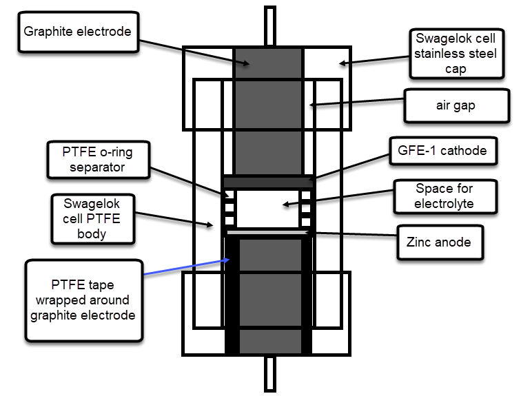
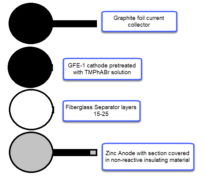
During my journey to understand and built better Zn-Br batteries I have constructed batteries using both separator and separator-less setups. In the separator containing setups there are layers of non-woven fiberglass tissue paper between the anode and cathode while the separator-less setups use PTFE o-rings as spacers to maintain the distance between the cathode and anode constant. Through my experience with both of these setups I have gained some useful experience that I am going to share within this post. More specifically I will be showing you a list of pros/cons for each architecture.

Image showing cell structure for separator and separator-less setups.

Non-woven fiberglass separator containing setup

Pros:

  1. Electrolyte is absorbed within the separator, therefore the cell can be moved freely for short periods of time without issues.
  2. Since the separator is solid it can be compressed more, leading to better battery characteristics.
  3. Compression is homogenous through the entire cell, which makes devices more reproducible.
  4. There is no spacer to keep electrode distance so all the effective cross-section can be used which leads to a more efficient use of cell volume.
  5. Slower diffusion of bromine across the device, which leads to slower self-discharge.
  6. Easily scalable.

Cons:

  1. Cell cannot be easily maintained or electrolyte easily replaced.
  2. Dendrites irreversibly damage the separator since the separator is physically torn by the zinc dendrites.
  3. There can be significant edge effects at the edge of the separator, as charges flow more efficiently around these areas since their interaction with the separator is weaker.
  4. Absence of important edge effects in the device as diffusion speed is likely constant through the cross-section.

PTFE o-ring spacer setup

Pros:

  1. Faster ion diffusion due to the absence of any additional material between most anode and cathode which can lead to better charge characteristics.
  2. Electrolyte can be replaced easily by opening up the cell and refilling or washing the cell components.
  3. Zinc dendrites are not irreversibly destructive, causing only self-discharge issues as they reach into the cathode. When the battery is at rest dendrites tend to re-dissolve as bromine diffuses from the cathode to the anode.

Cons:

  1. Compression of a spacer setup can cause a carbon felt cathode to be compressed into the o-ring, effectively getting closer and closer to the anode and sometimes cutting the cathode material. This effect is difficult to control well, which causes reproducibility problems between devices.
  2. The devices cannot be moved because sloshing of the solution can cause important issues, such as self-discharge, to accelerate exponentially.
  3. Due to the spacer taking some volume in the device, the amount of usable coss-section decreases, which causes substantial losses in device energy density.
  4. Not easily scalable as electrodes will tend to sag when larger cross-sections are used, therefore requiring the design of a scalable spacer design (like a PTFE grid) which is likely to be expensive.

After thinking a lot about the above characteristics, it seems to me that the main important disadvantage of the spacer setup is its vulnerability to become damaged irreversibly by the appearance of zinc dendrites. If these are not a substantial issues, then a fiberglass separator setup would be significantly better approach – both in terms of cost, reproducibility, scalability and performance – relative to a PTFE spacer based setup using no separators.

Let me know what you guys thing about the above!

Zinc Bromine Batteries: First successful static cell using a non-aqueous solvent for Br sequestration

During my latest experiments, I have moved to an inverted geometry setup, given that hydrogen evolution is a problem that needs to be eliminated for cells that are expected to last for long periods of time. However, an inverted geometry carries with it the problem of more favorable diffusion of elemental bromine – due to the fact that the cathode is now on top – reason why aggressively sequestering bromine is now a top priority.

In order to do this I have been trying to use a TBABr saturated propylene carbonate (PC) solution (which I will be calling TBABr-PC). My expectation was that by soaking the cathode in this solution I would be able to prevent any elemental bromine formed from escaping. The TBABr-PC behaves a lot like an ionic liquid (it’s > 50% TBABr) so its high conductivity and much higher affinity for elemental Br should allow the battery to work properly while keeping all the Br2 from reaching the anode or the aqueous electrolyte.

After mixing an aqueous Zinc Bromide solution with a TBABr saturated PC solution, two new phases form, with the organic phase now at the bottom.

The problem with these initial tests was that the battery seemed to suffer from initially low conductivity and charge retention with substantial changes through time that appeared to improve on these parameters. My guess was that there was a lot of ion migration between the initial TBABr-PC and the ZnBr2 aqueous electrolyte and that the battery was just not stable while these were happening.

To solve this issue I prepared 10mL of 1.5M ZnBr2, 1% Tween 20 solution and mixed them with 2mL of TBABr-PC. The TBABr-PC was initially above the aqueous electrolyte, as expected from its lower density. After adding them together I then proceeded to mix them vigorously, which lead to the separation of two new phases. The PC phase now became denser, with the aqueous phase resting on top. This shows that there was some transfer of ZnBr2 into the PC solution, although thankfully the phases do remain immiscible.

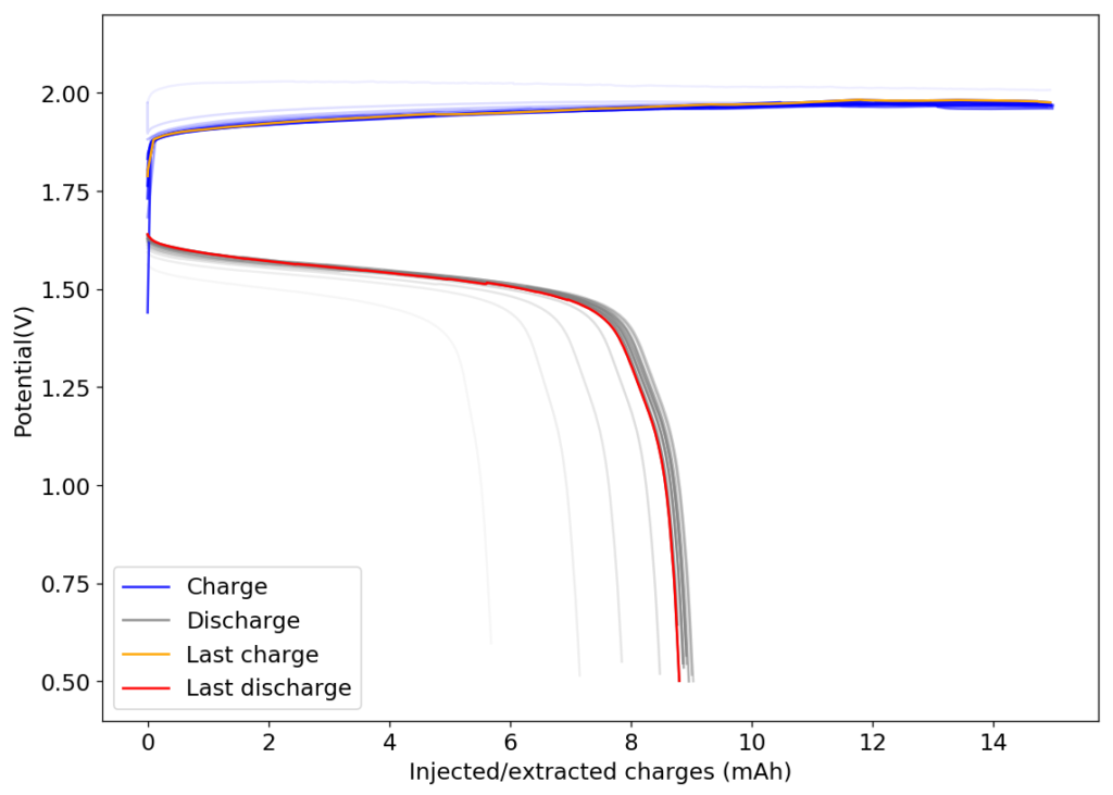
First cycle of a cell using a GFE-1 cathode saturated with the bottom phase resulting from mixing a saturated TBABr-PC solution with a 1.5M ZnBr2+1% Tween 20 solution.

I then proceeded to fill an inverted cell with the top solution, saturated a GFE-1 cathode with the bottom solution and placed the saturated GFE-1 cathode on top before compressing the Swagelok cell. The cell had no separator but 4 PTFE o-rings as spacers. Since the PC had proved to have low conductivity before, I decided to cycle this device at 5mA to 15mAh. You can see the result of the first cycle above.

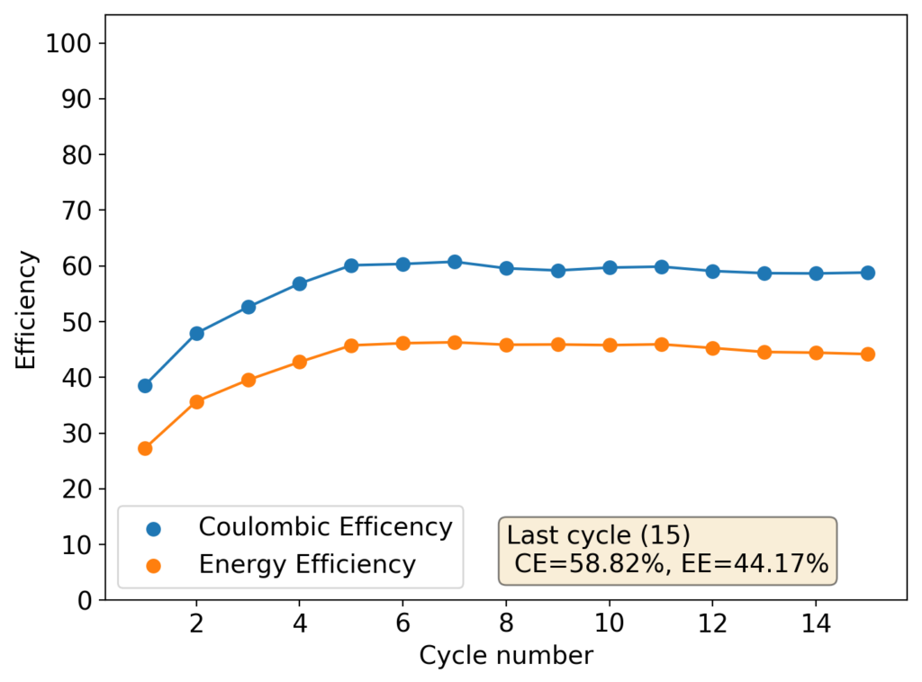
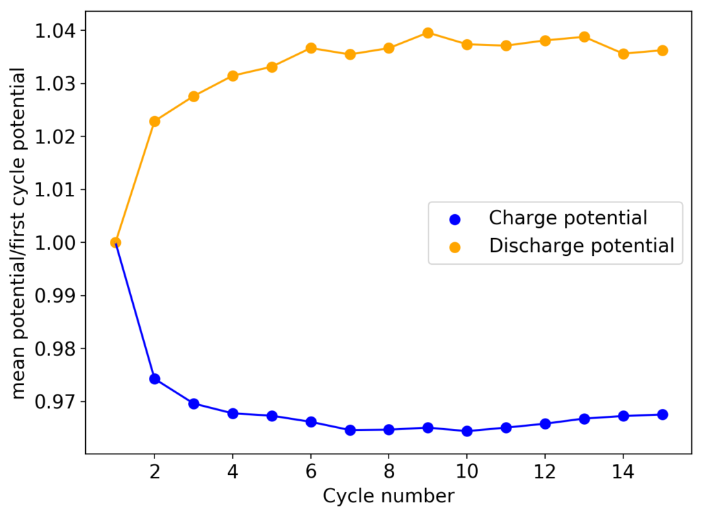
Although the CE and EE are now significantly better than before, there are still big questions about how a cell like this will evolve over time and whether the TBABr-PC is as effective at sequestering elemental bromine as I believe it might be. The fact that the organic phase is now denser also begs the question of whether the organic phase will just pool at the lower half of the cell with time. Hopefully affinity for the GFE-1 cathode is high enough. A potential solution to this problem is to try this experiment again with a 3M ZnBr2 solution, which is going to have significantly higher density.

I will first cycle this cell for some time to gauge its stability before running a self-discharge experiment to test whether the TBABr-PC does significantly impair self-discharge of the device.

Zinc Bromine Batteries: First results ever using Propylene Carbonate

Earlier this month, I wrote an article about the use of non-aqueous solvents in Zn-Br batteries. The only published result I could find was an article dealing with Zn-Br flow batteries using propionitrile as the catholyte solvent but I wanted to avoid the use of propionitrile due to its toxicity and scarcity (hard to find/buy for an individual in the US). However I thought propylene carbonate (PC) could be a suitable replacement, so I bought some to test whether this was true or not.

The first experiments I carried out were to figure out whether PC could be used as the sole solvent within the battery. Sadly the solubility of ZnBr2 is not high enough – at most in the 0.5-1M range at 20C – and the conductivity of these ZnBr2 solutions was also not high enough, with very noisy charge/discharge curves with very high charge voltages that retained almost no charge at all.

The solubility of both TMPhABr and TBABr in PC is better, although TBABr is by far the most soluble. With TBABr I was able to achieve saturated solutions with almost 50% of TBABr, giving them a very decent amount of conductivity. Sadly this wasn’t enough to make PC usable as a single electrolyte though, as the bad behavior of the charge/discharge was also apparent when using this as the sole solvent.

Charge/discharge curves for a cell built with a 1% Tween20 + 1% PEG 200 + 1.5M ZnBr2 electrolyte with a GFE-1 cathode fully saturated with a 50% TBABr in PC solution.
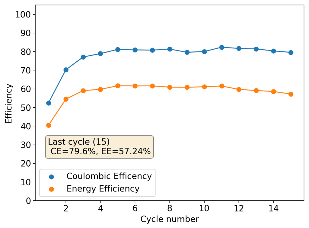
Evolution of CE and EE values for the curves shown before.

The idea then came to use this concentrated PC TBABr solution to saturate the GFE-1 cathode and use this in an inverted cell. It is interesting that although PC is infinitely miscible with water, a 50% solution of PC TBABr is actually not miscible with a 1.5M ZnBr2 solution in water. This is because the affinity of TBABr for PC is much higher than that of ZnBr2 and the affinity of ZnBr2 for water is also significantly higher as well.

This experiment was better behaved with actually measurable charge/discharge curves. I did 4 curves charging/discharging to 15mAh at 15mA – the results are shown above – with the best CE and EE values being 61% and 25% respectively. The charging voltages do show that the internal resistance is significantly higher than when using water so there is likely a lot more of hydrogen evolution at the anode. The generation of elemental bromine at the cathode is also probably significantly slower, given the much higher viscosity and lower conductivity of the PC electrolyte.

Given the higher charge density used, I thought It might be the case that the PC electrolyte is just not able to support as high of a current density as the normal aqueous electrolyte and therefore a much lower charge density needs to be used to use this successfully. I am going to be evaluating this hypothesis within my next few tests.