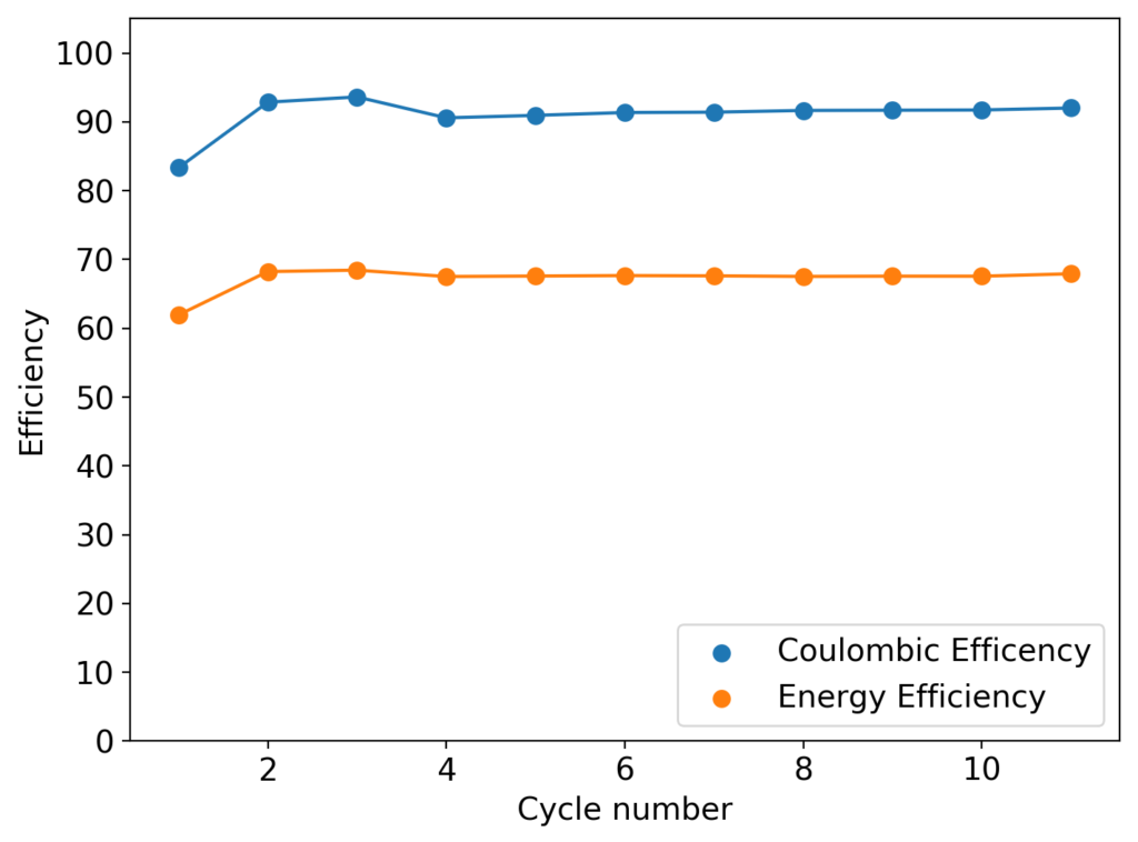
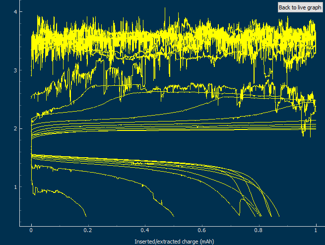
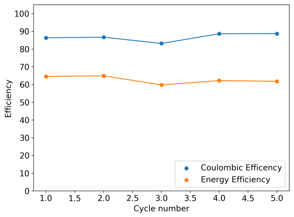
As I showed in my last article on Zn-Br batteries using a Tween20+PEG-200 electrolyte, the batteries had no issues with dendrite production on the zinc anode but faced substantial deterioration of both the charging and discharging voltages as a function of time. I repeated the experiment using a Zinc anode to see if this phenomenon was consistent. The tests below were carried out for a battery that used a GFE-1 cathode pretreated with 10% TMPhABr and an electrolyte containing 1% PEG-200, 1% Tween 20 and 3M ZnBr2. The cell used a 0.2mm Zinc anode and graphite electrodes within the Swagelok cell.

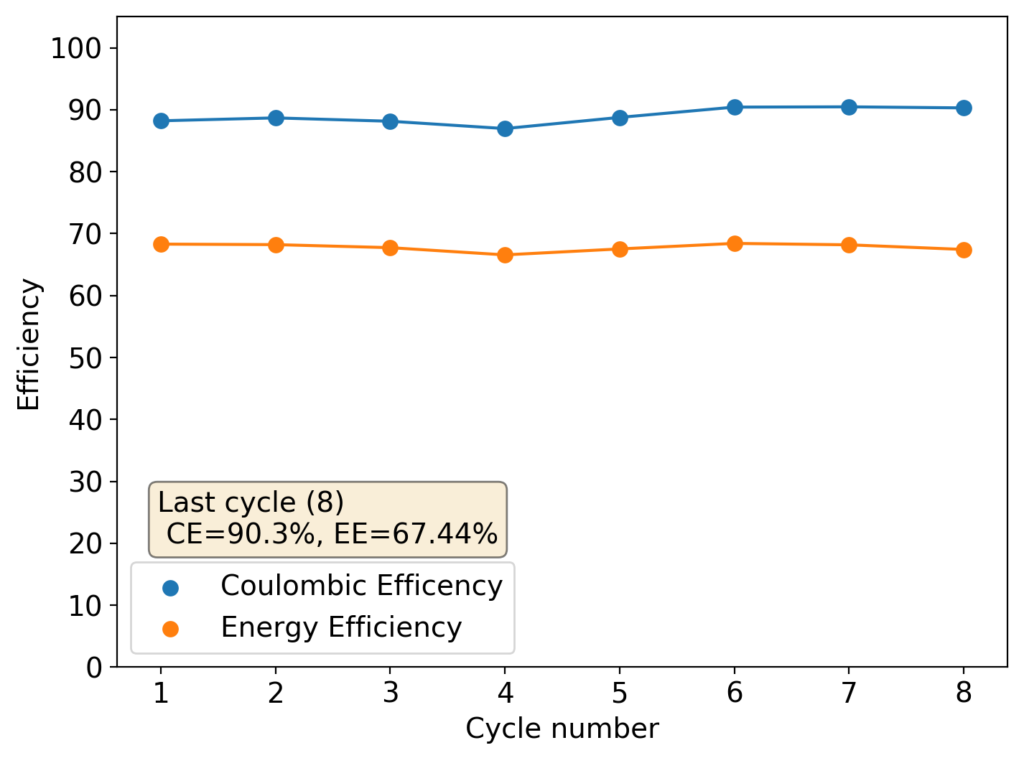
As you can see in the images within this post, although the CE and EE values of the battery remain fairly constant through the test, the mean charge potential increases and the mean discharge potential decreases as a function of the cycle number. This is showing that there is an overall increase in the internal resistance of the cell as a function of time, which appears to be linear and doesn’t seem to become smaller with time. Other cells that were charged to even larger numbers of cycles continued to show this deterioration, up to the point where the EE and CE of the cell started to decay and the cell started to fail.
This behavior points to some irreversible process happening within the device that is fundamentally affecting internal resistance. This has to be either a surface modification of the electrodes or an irreversible loss of conductivity in the solution. The first can happen due to bromide/perbromide interactions in the cathode, zinc oxide deposits in the anode caused by a local increase in pH due to hydrogen evolution or even the appearance of some insoluble polymers in the cathode due to electrochemical reactions of the additives.
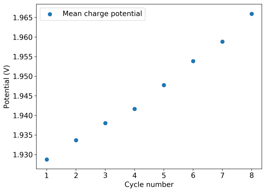
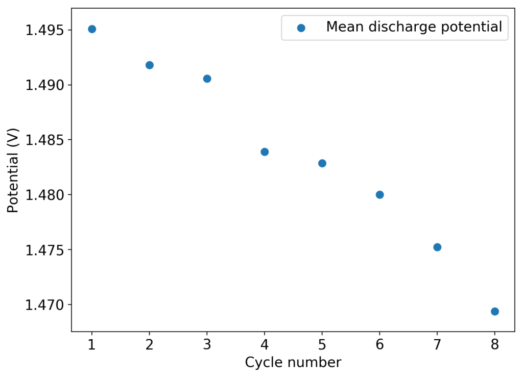
There is some evidence that cathode structure does deteriorate with time under the cell conditions. There is a significant amount of graphite that can be wiped off the Swagelok cell electrode after opening up the cells – while the graphite electrode was sanded and completely clean upon cell fabrication – which might point to the electrode itself or the GFE-1 cathode material degrading. I am currently running an experiment using a titanium electrode with a GFE-1 cathode to rule this out.
About the stability of the additives and sequestering agent, it might be worth it to carry out some cyclic-voltammetry (CV) experiments to investigate the stability of the organic additives being used to see if any of them can fundamentally degrade under these conditions. The TMPhABr could be especially susceptible, given its aromatic amine character. If the sequestering agent can deteriorate under these conditions, then we might be unable to use it as an effective agent and we might need to resort back to TBABr or TPABr. The Tween 20 might also be electrochemically vulnerable, so this additive also needs to be studied in this manner.


