Flow batteries are a great approach for large scale energy storage. While in a battery the amount of energy is constrained by the mass of the anode and the cathode, in a flow battery the cathode and anode are stable electrodes (most commonly graphitic foams) and the energy is stored in solutions that are pumped through these electrodes.

Many of the lowest cost approaches to the chemistry of a flow battery are unable to fully take advantage of this, because they reduce a metal to its solid form on the anode. Approaches using Fe and Zn where this happens are common. The deposition of a solid metal then creates additional issues with both passivation and with dendrites, which can end up shorting the flow battery down the line.
To solve these issues, we need a chemistry where both the oxidation and the reduction happen in solution (with no solid formation on the electrodes). Additionally both of the half-reactions need to be reversible. From a DIY perspective, they should ideally happen under mild conditions and, to make things even more difficult, we need materials that are low cost and that can be easily purchased.
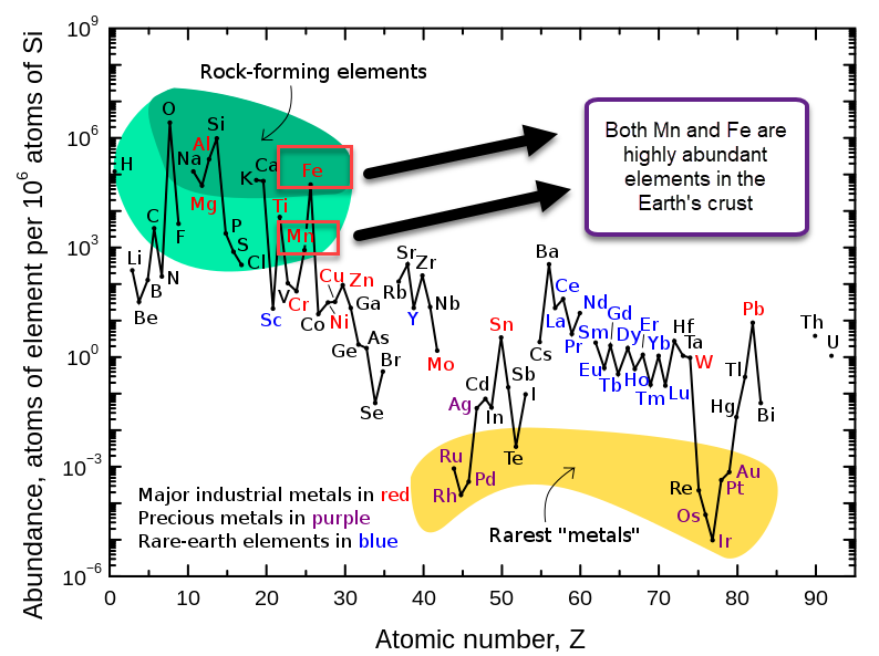
Manganese (Mn) and Iron (Fe) are some of the most common elements on the Earth’s crust, so they fulfill the cost issue. However, when building a flow battery with Mn, we find that the oxidation reactions that Mn is involved in generally involve the formation of insoluble Mn oxides. This happens because Mn3+ is generally unstable in solution and reacts with water to create Mn2+ plus an Mn4+ oxide or hydroxide.
However, a few papers have been published on the use of Na2Mn(EDTA) in flow batteries. This chelate – a commonly available fertilizer – protects the Mn3+ from reacting with water and enhances the reversibility of the reaction. Given the potential where the oxidation of Mn(EDTA)-2 happens, I thought it could certainly be coupled with the reduction of Fe3+ to create a flow battery. Additionally NaFe(EDTA) is also a low cost highly available fertilizer we can use.
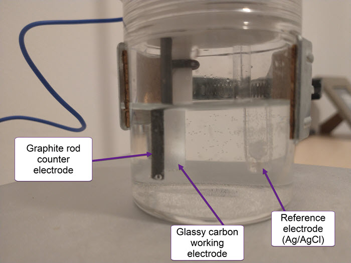
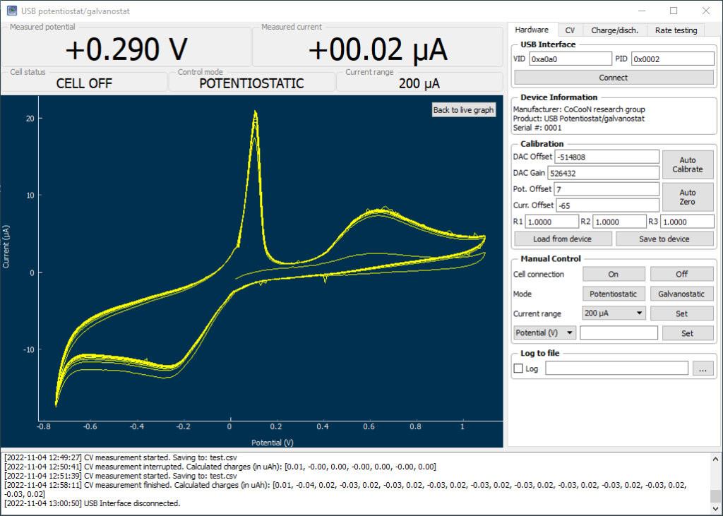
On a previous post, I spoke about a setup for electrochemistry that I created, which allows me to carry out several measurements in solution. Using cyclic voltammetry of a solution containing Na2Mn(EDTA) and NaFe(EDTA) I was able to characterize the system and obtain half reaction potential values for the Fe and Mn reactions mentioned above.

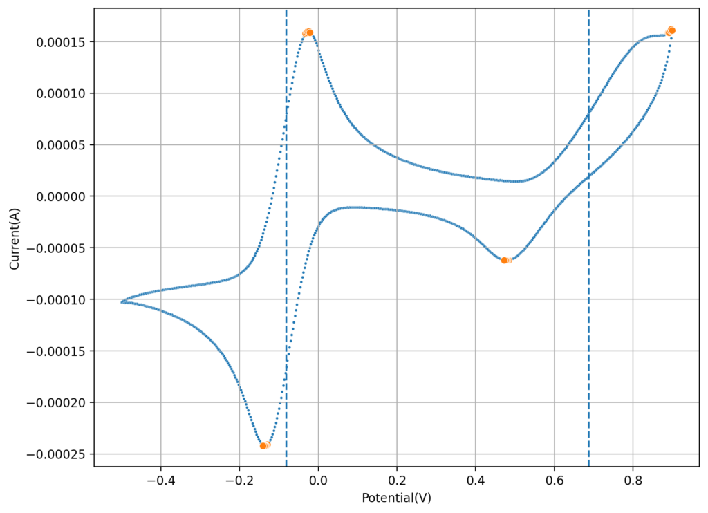
If we add the two potentials above, we can obtain the expected potential for our battery, which would be 0.74V. This is not very high, which means that the energy density of our flow battery system is going to be low. If we consider the solubility of both compounds, then we expect the power density of this battery to be around 10Wh/L. This means that you would need 100L of 0.5M NaFe(EDTA) and 100L of 0.5M Na2MnEDTA to get a 1kWh battery. This means 18.3kg of the Fe salt and 19.5kg of the Mn salt. You will also need around 35kg of NaCl as a supporting electrolyte.
At retail you can find both Fe and Mn salts for a price of around 6-15 USD/kg (if you buy 25-55lb bags). On the low end this means the cost would be 226.8 USD/kWh and on the high end 567 USD/kWh at a retail price point. In pallet amounts, the cost for both is around 2 USD/kg, so the cost goes down to 75.6 USD kWh. Note that this is only for the Fe and Mn salts.
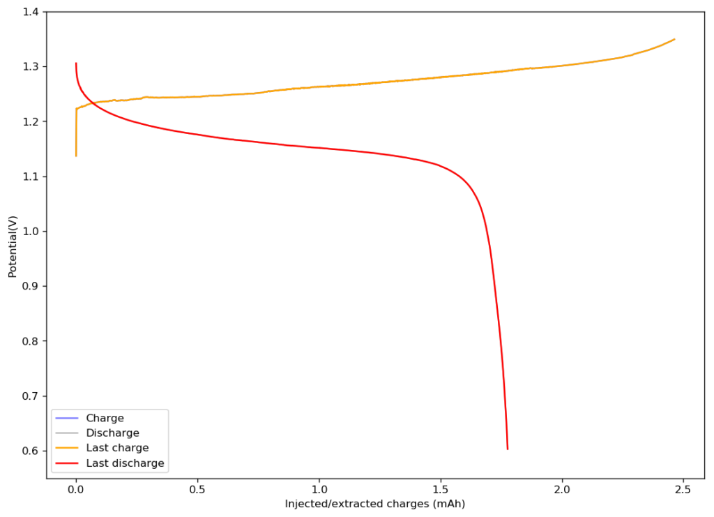
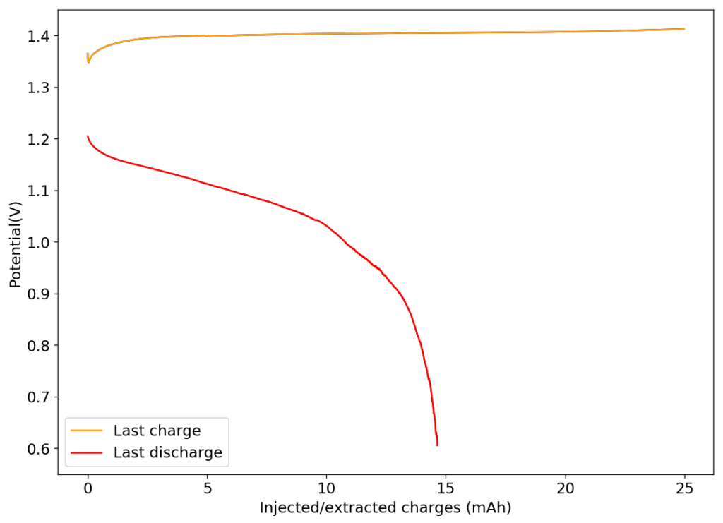
The challenge is now to create a small electrochemistry setup with two electrochemical chambers separated by an ion exchange membrane where we can carry out some initial charge/discharge measurements and measure the cross-over of ions without the need to do any sort of pumping. This is also going to involve the design of some DIY low cost membranes, since Nafion membranes would be extremely expensive. Additionally, since the conditions are so mild (pH 5-6), we can use some modified PVA or cellulose cation transport membranes that can be produced for very low cost.

