I wrote a blog post about some of my first tests of the electrochemistry of the Fe-EDDHA|Mn-EDTA system and how I planned to build a flow battery using this chemistry. I have since been able to setup a flow battery and perform some initial experiments. So far, there are several fundamental problems with the above chemistry that strongly affects its viability. I will discuss these problems below.
Fe-EDDHA solubility and pH. The Fe-EDDHA is more soluble at more basic pH values and its solubility at neutral pH is limited to perhaps only 0.1-0.2M. Furthermore, there are several less soluble impurities present – different isomers of the EDDHA – which have to be filtered before the cell is operated. Additionally, the pH changes substantially upon charge/discharge, which causes problems with the Mn-EDTA side (you’ll see later on).
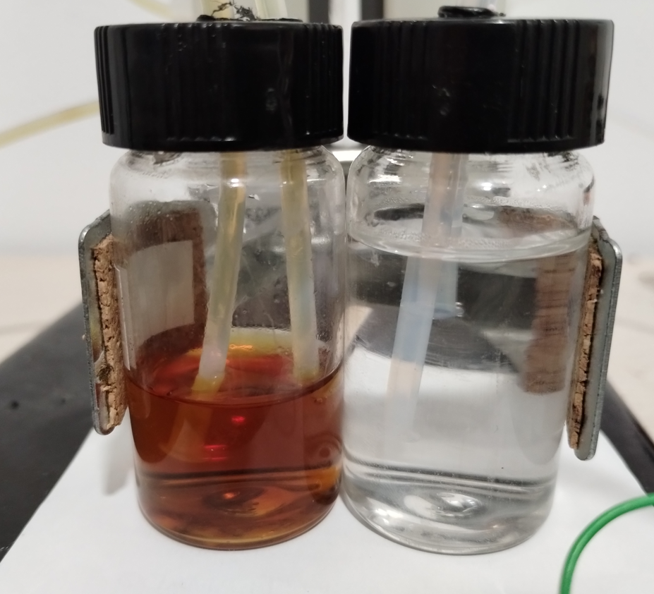
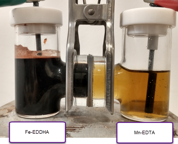
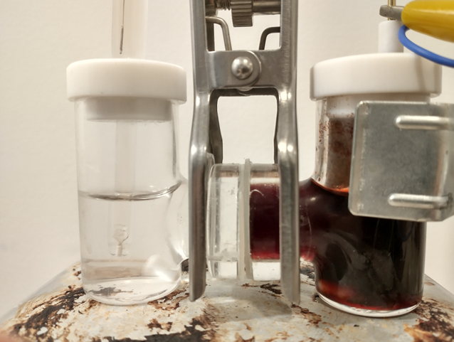
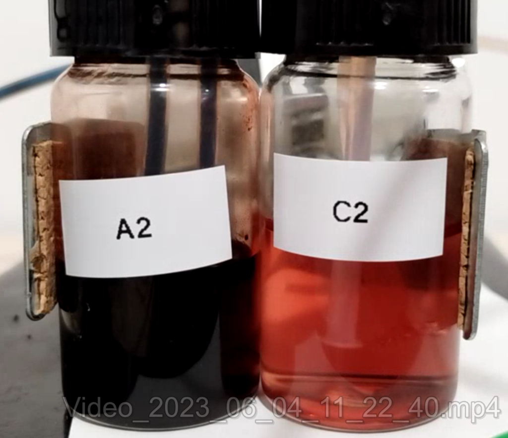
Difficulty in working with Fe-EDDHA solutions. The solutions of Fe-EDDHA are very deeply red, basically black at the concentrations we’re working with here. This means that it is very hard to tell if there are any insoluble substances in the solution. It is also hard to tell the charge state of the solution, as it will only slowly become more transparent as the Fe-EDDHA is reduced to its Fe(II) form.
Fe(II)-EDDHA sensibility to oxygen. Once the Fe-EDDHA is reduced in the anode, the liquid becomes incredibly sensitive to any oxygen dissolved in the solution, which will quickly oxidize the Fe(II)-EDDHA back to Fe(III)-EDDHA. Given that I currently have no means of purging my system of oxygen, this makes it impossible for me to run flow batteries using Fe-EDDHA right now in a reliable way.
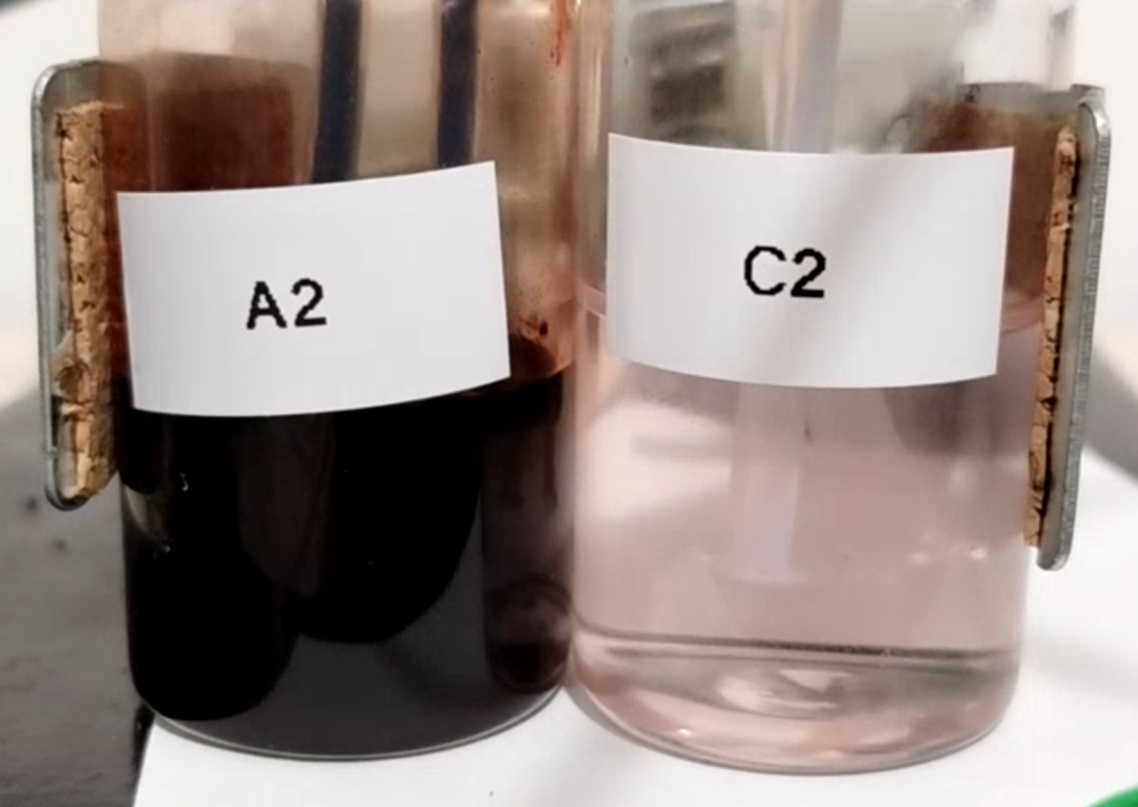
Mn-EDTA stability at higher pH. The oxidized form of Mn-EDTA, which is Mn(III)-EDTA, is red at a pH below 6.5 and yellow at a pH above 6.5 (you can see that yellow in a previous post). However, the yellow molecule is extremely unstable, therefore it is very important for pH to remain below 6.5. However, at a pH below 6.5 the solubility of the Fe-EDDHA drops substantially. The differences in pH between charge and discharge means that both systems are virtually incompatible, because as the Fe-EDDHA charges it induces changes of pH that very negatively affect the decomposition of the Mn-EDTA catholyte.
For all the above reasons, I decided I no longer will explore the Fe-EDDHA|Mn-EDTA system, as I currently don’t have the technical setup that is necessary to properly study it. Furthermore, the low solubility, difficulty of working with the Fe-EDDHA solutions and the problems with pH, make this system more complicated than I was hoping for, especially in a system I hoped to be simple for DIY.
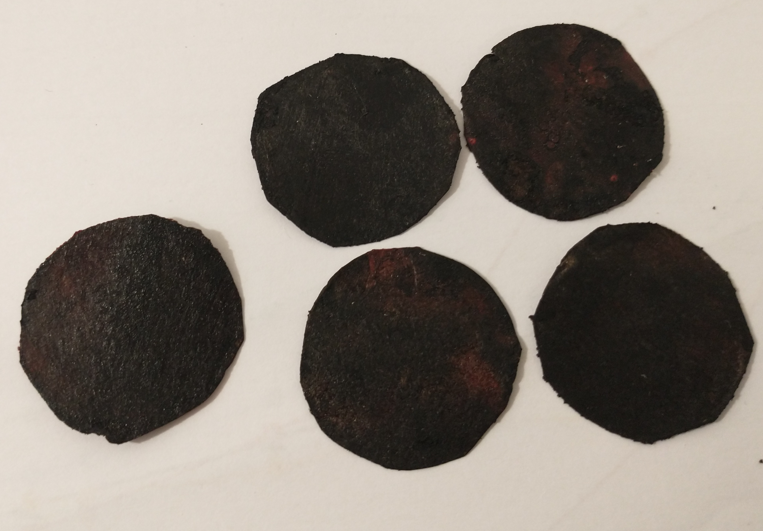
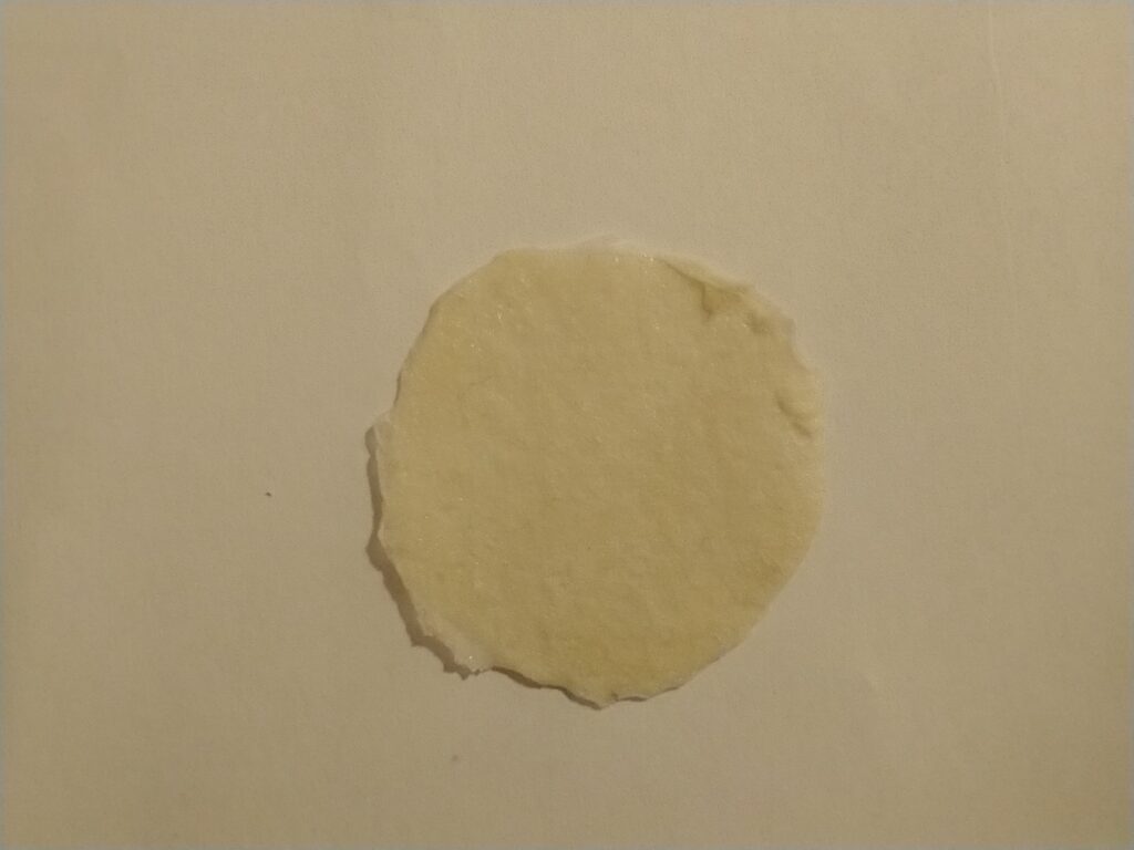
I will continue to study flow batteries based on Mn chemistries, including Mn-EDTA (as these are very interesting), but I will likely change the anolyte to something that is more aligned with my current setup. Most likely I will have to compromise and use a potentially higher density, low cost anolyte, that will involve plating a metal on the carbon felt anode, like Zn. Hopefully in this manner I’ll be able to find a low cost setup to bring a DIY solution with a capacity at least in the 10-20Ah/L range.