My original idea was to create a flow battery without Vanadium that would contain no metal deposition reactions on either the anodic or cathodic sites. This would be a true flow battery, in the sense that energy capacity would be completely decoupled from power capacity. It would also be compatible with a symmetric electrolyte which would allow the use of microporous membranes. There is currently no low cost flow battery – to the best of my knowledge – that fulfills these criteria, outside of Fe/Mn (with Fe/Cr and V being the only options).
My original idea was to use easily sourced FeEDTA and MnEDTA for this purpose. However it became clear that there are important solubility issues with FeEDTA and MnEDTA plus significant stability issues related with the Mn3+ EDTA chelate, which prevented this battery from actually working. While both FeEDTA and MnEDTA had been used in different flow batteries, no one had put them together on any published research — now I know why.
However, there was a paper published in 2022 that was able to use a symmetric Fe/Mn chemistry by employing Fe chloride and Mn sulfate in an acidic media with a special proportion of sulfuric acid and hydrochloric acid. I wanted to try this out to see if I could actually get an Fe/Mn chemistry that worked. The paper goes into the importance of the hydrochloric acid to generate stable Mn3+ species, but doesn’t say anything about the importance of the sulfuric acid, so I decided to try a hydrochloric acid only approach for starters and see if the CVs showed reversible Mn chemistry.
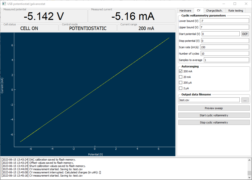
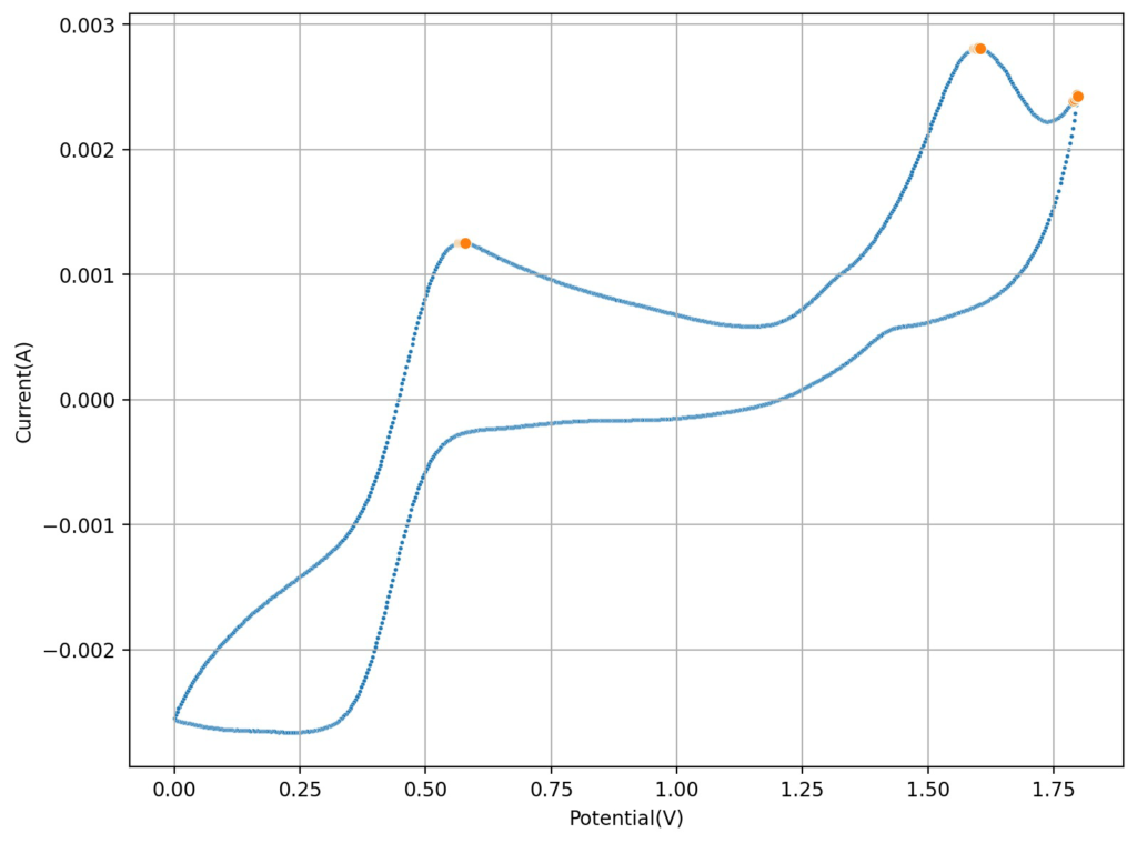
The first CV I carried out is shown above. This solution was prepared by using 5mL of 15% HCl, 5 mL of 40% FeCl3 and 3g of MnCl2. You can see the reversible reaction for the Fe with a standard potential near 0.45V, you can also see an Mn oxidation peak near 1.6V with no evident reversibility (no reduction peak). This is classic for the formation of MnO2 and its subsequent conversion back to Mn2+ with generation of Cl2 in concentrated hydrochloric acid. Gas bubbles on the working electrode were also evident, which further supports this hypothesis.
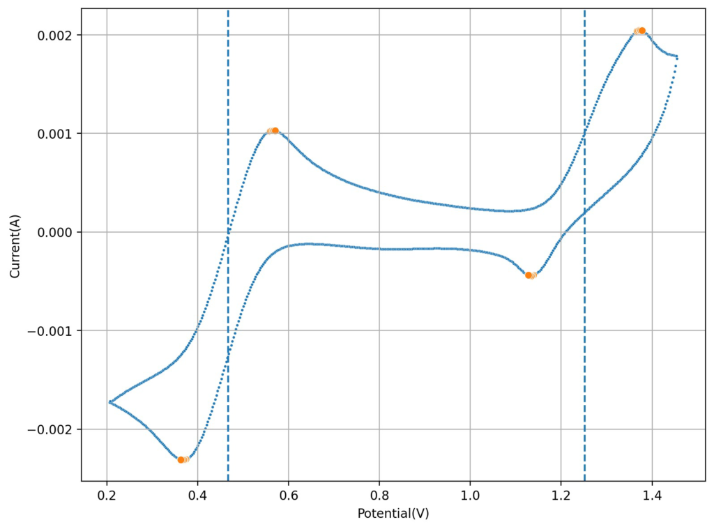
I then tried lowering the concentration of the HCl to see what would happen to the CV. Interestingly enough, when going with a 0.6M concentration, I saw the appearance of a reversible reaction with a standard potential near 1.25V, which is near the potential that is mentioned on the paper. This peak also shows significant reversibility, with the corresponding reduction peak appearing near 1.15V. The difference between these two standard peaks is also 0.775mV, which is close to the open circuit potential reported for the flow battery within the paper I mentioned before. This solution was 1mL 15% HCl, 3g MnCl2 and 5mL of FeCl3 40%.
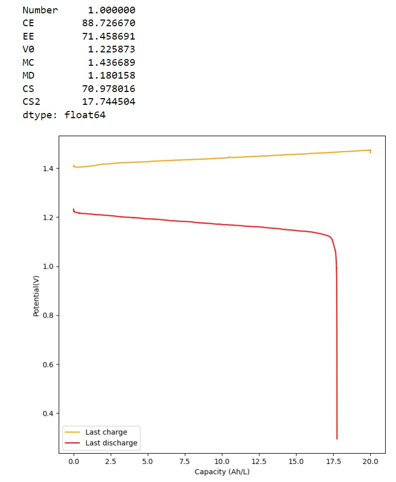
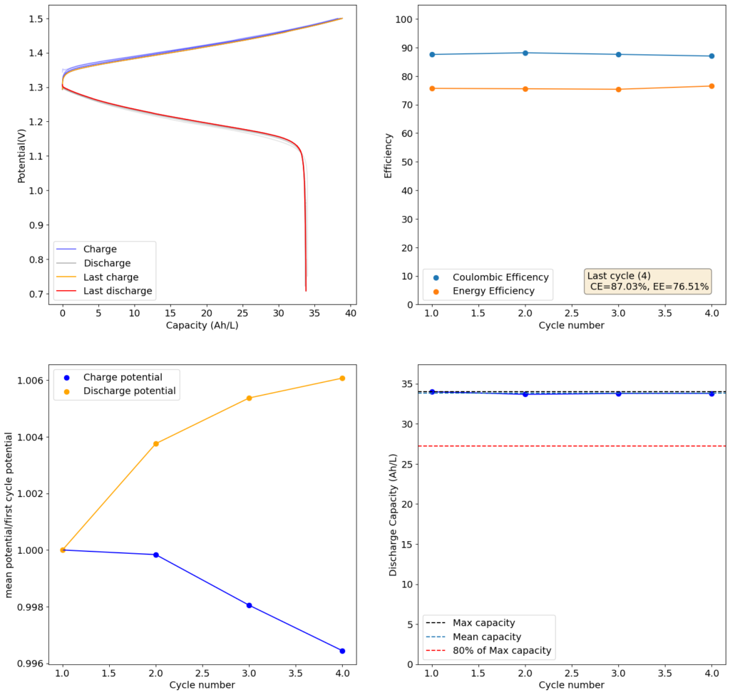
Upon charging, acid will become depleted from the cathodic side, which might be why the sulfuric acid was used on the paper to generate proper cycling (as MnO2 would start forming if the pH became too basic). Interestingly enough, volumetric capacities aren’t mentioned in the paper (just mAh of charge). Using their values of 5mL of volume per side (total volume of 10mL) their discharge capacity goes from 1-2.5Wh/L, which is 10x lower than the standard for Vanadium batteries. This means that – while the Mn3+ chemistry is reversible – very little of the Mn is actually accessible (less than 10% at a 1M concentration).
The acid balance here is fundamental, so you likely need just the right amount of HCl to make Mn3+ stable, but not enough as to make the oxidation of Cl– to Cl2 very favorable. If possible I would like to stay with a battery with only chlorides, as the inputs are easier to source (sulfuric acid is hard to get in many places), so I will try to cycle the above chemistry soon as see if it is actually feasible. On another note, Mn3+ reacts with cellulose quite quickly, so I will have to use a proper microporous separator – like Daramic – instead of the photopaper I have been using for Zn/I experiments.
Things are not looking very good for an Fe/Mn chemistry.