During the past couple of years we have been working on the design of a small flow battery kit for the study of flow batteries (you can read a previous post about it here). With the help of an NLNet grant, we have fully developed the first two versions of our small scale kit – with the second one achieving even longer scale tests – and are now working on the development of a larger surface area kit that can be used to study flow batteries or build flow battery applications at a relevant scale for practical power storage.
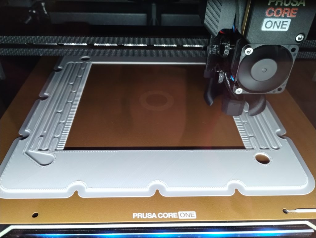
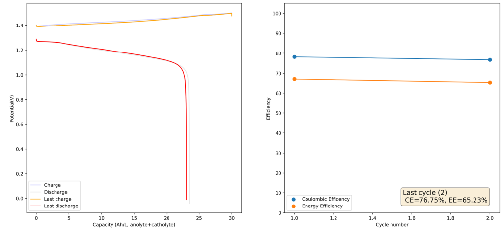
This new large area setup – which we have discussed in our forum – is now moving out of the design stage thanks to the acquisition of new systems for both 3D printing (Prusa Core One) and vinyl cutting (Cricut Maker4) that are allowing us to move to their in-house fabrication and testing. The new cell is designed to be compatible with the area of 3D printing beds and features an active area of 13.5×13.5cm, which is 182.5cm2. In practice this means a single cell will be able to handle a capacity of nearly 22Wh when using the Zn-I chemistry used in our small scale design.
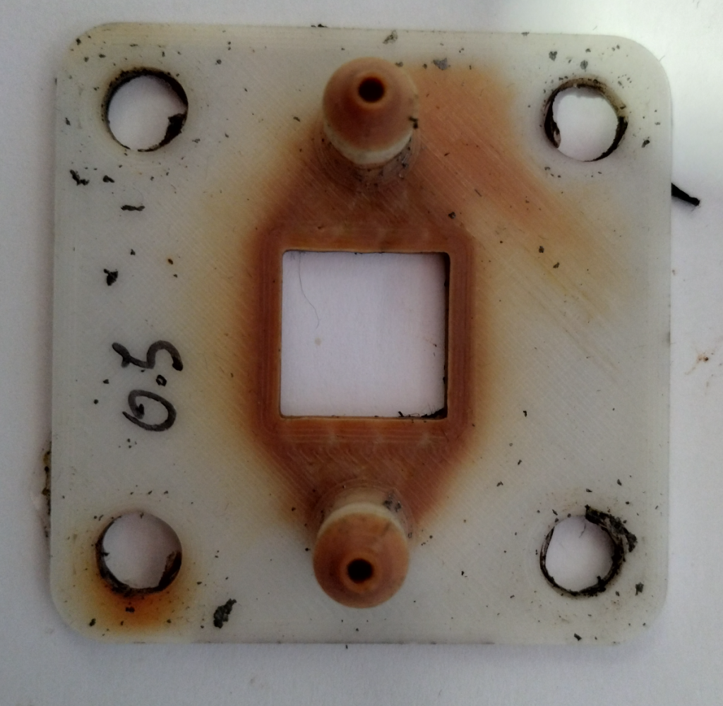
We borrow some of the features that worked great for our small scale kit – like using a polypropylene enclosed flow frame – and add features that are needed for a scalable design (like all entry/exit points on the same side, stacking compatible design, etc).
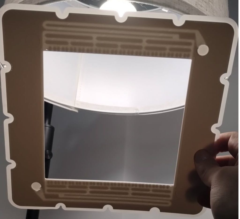
The fabrication of these pieces is especially challenging due to their size and the complexity of the flow fields in them. The flow fields have to follow complex paths to prevent the creation of large shunt currents within the device. A really good 3D printer with a heated enclosure is required to be able to print this in polypropylene with no warping and good enough resolution. Even with such a printer, a lot of fine tuning is still required to achieve the low level of surface roughness and high level of water tightness that is needed for this particular application.
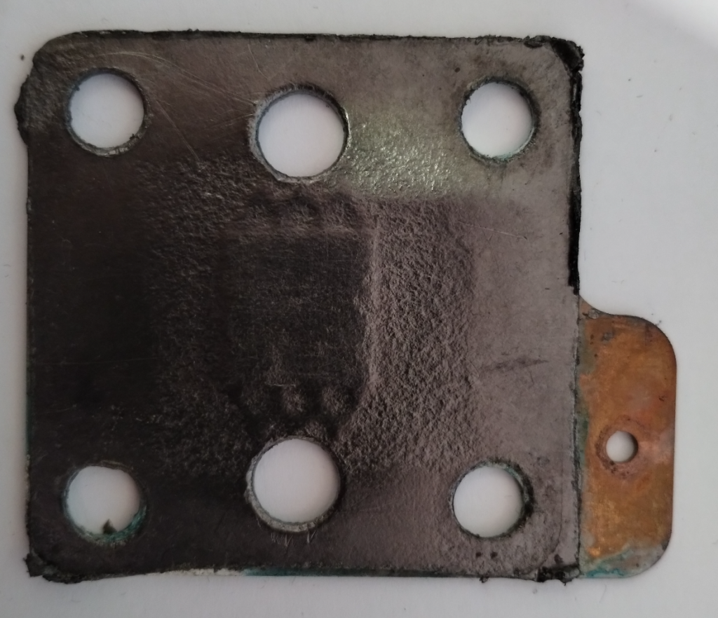
While we are thinking about the potential of using heat welding or even adhesives to be able to put the cell together, the easiest first approach will be to use the same silicon gaskets as we used for the fabrication of our initial cells. To cut our gaskets in house we are using a Cricut Maker4 vynil cutter, which is able to make this high precision cuts without any problems.
With these materials now fabricated, we are now close to putting together our first tests of a larger scale flow battery cell. The idea of these initial tests will be to test the cell for leaks and make sure we can circulate water without problems before we try to run any active materials. We will be using thick wood as endplates for this initial test, as this is the easiest to source, hard material, that can be used. Thanks to our use of fully enclosed gaskets, the end plates will also have zero contact with any water or active materials.

This flow battery kit work is being funded by the Financed by Nlnet’s NGI0 Entrust Fund. We are also collaborating with the FAIR Battery project.