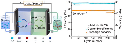
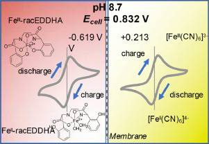
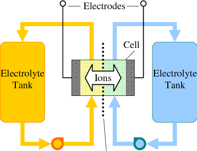
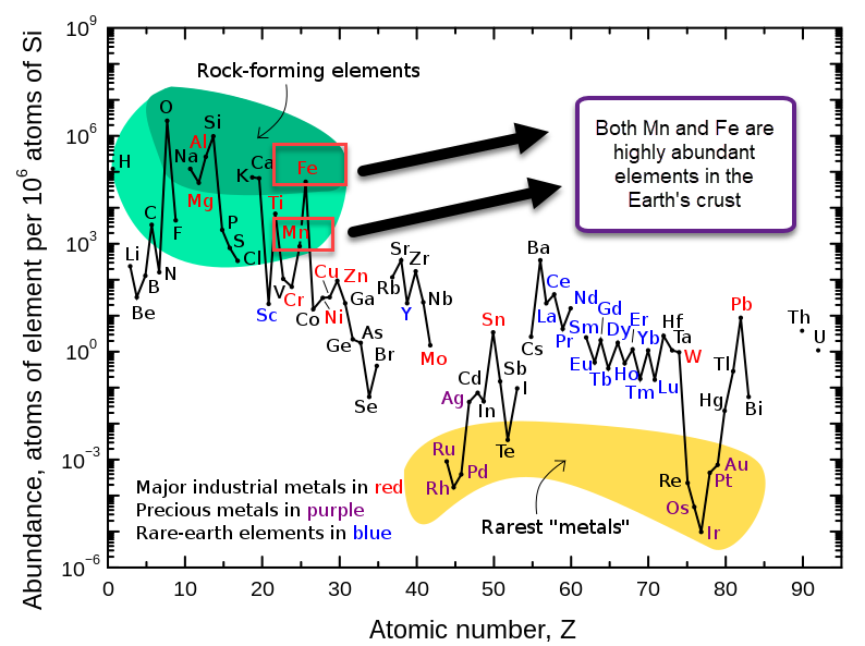
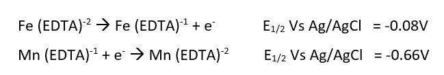
In previous posts (here and here), I have talked about my goal to create an Fe/Mn flow battery and how to do this I will need to create a cation exchange membrane to use instead of Nafion. In this post I will talk about what I have achieved so far, which is the first iteration of a PVA based cation exchange membrane.
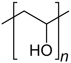
Early on, it became clear that polyvinyl alcohol (PVA) was going to be the easiest polymer choice, as it is readily available and easily to functionalize. Phosphorylation also seemed as the easiest route towards functionalization, as highly concentrated phosphoric acid is easy to get and urea catalyzed phosphorylation reactions of PVA are already well known. The introduction of phosphoric acid esters provides the ability of the membrane to repel anions and allow only cation transport.
My first problem creating a membrane of this sort had to do with casting PVA films and being able to peel them off. These membranes are extremely sensitive and can easily stick to glass or to themselves, making the fabrication process difficult. I tried casting on glass petri dishes – with mold release – and was unable to remove them without breaking them. A friend suggested casting on Al foil instead, so I will be keeping this for a future experiment.
Furthermore, the few times I was able to successfully peel off films, the films then dissolved quite easily in water. Although I thought the phosphorylation of the PVA would provide some crosslinking, it definitely increases the solubility of the polymer in water, making things actually worse. Using things like aldehydes for crosslinking is not going to be work, but perhaps future experiments with boric acid or citric acid would help with this issue.
A breakthrough came when I realized that cellulose is also known to be phosphorylated with phosphoric acid plus urea and that it could therefore be cross-linked through a phosphoric acid ester with PVA. The cellulose could also provide a support, which would greatly enhance my ability to work with the PVA solids.
My fabrication process was as follows:
- To 15mL of ice cold distilled water add 1g of PVA, 1g of Urea and 1mL of 81-85% phosphoric acid. This is solution A.
- Place in a fridge for 48 hours, with occasional stirring/shaking. Surprisingly, cold conditions are much better for dissolving PVA because they discourage agglomeration.
- Wait till solution A is fully homogeneous, keep longer in fridge and shake/stir as needed.
- Dip a filter paper in Solution A. I used Stony Lab 101 but other fine grain filter papers should work just as well. Make sure all excess has dripped off and tap with paper towels to remove any excess.
- Place on a hot plate at 180C for 3min
- Flip it to the other side for another 3 minute.
- Repeat steps 4-6 once.
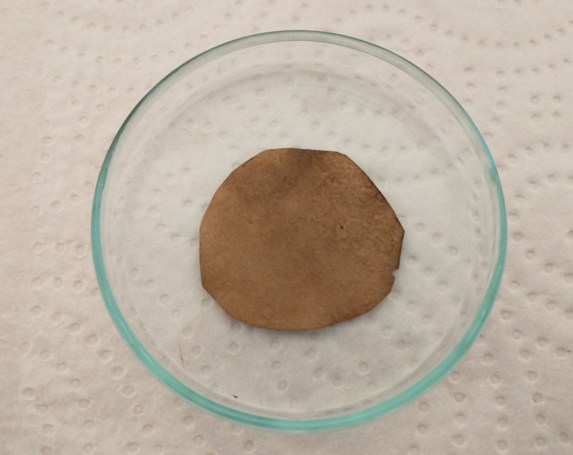
- Place on the hot plate with a petri dish on top (to keep it flat) for 1 hour.
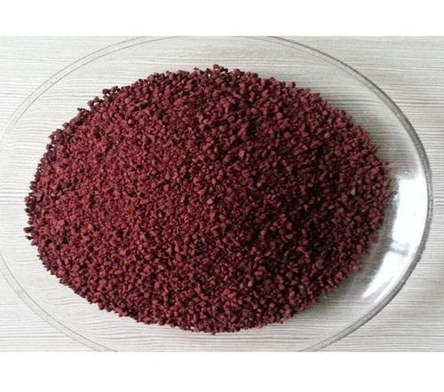
- The result should be as shown in the image above.
The process seems to work. The resulting membrane is not soluble in water, is sturdy and easy to manipulate and loses the micro porosity of the filter paper. It is quite brown, which means some oxidation has happened, but reducing the temperature or time leads to membranes that are not properly crosslinked, and dissolve quite easily (leaving just a porous cellulose membrane behind).
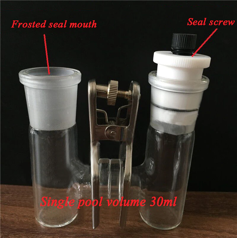
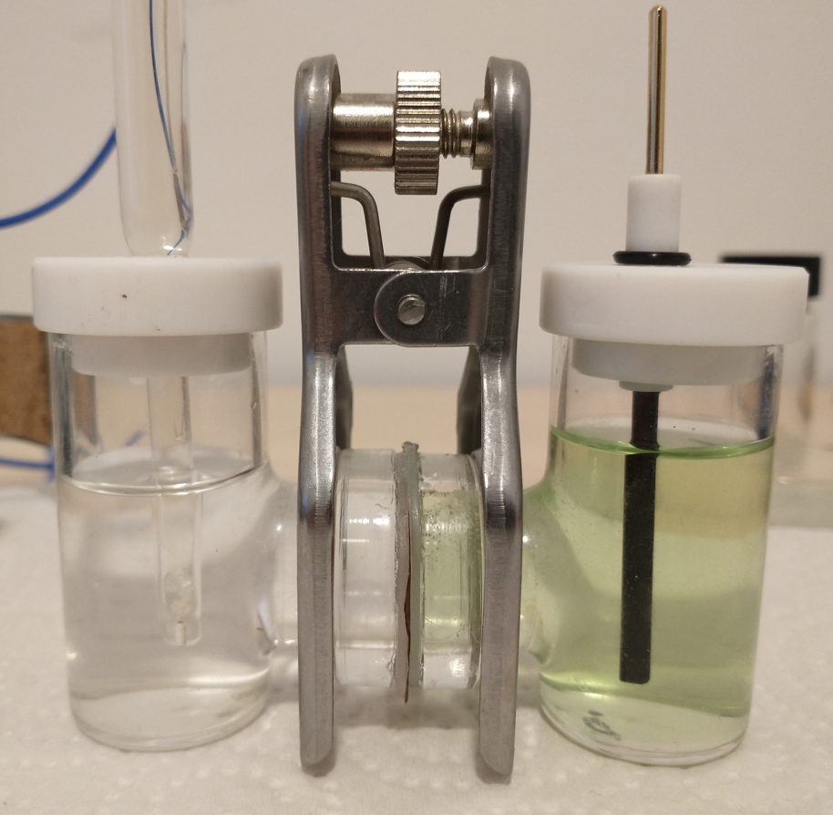
To determine whether the above membrane is in fact a cation exchange membrane, I can measure its permselectivity. To do this, I measure the membrane potential between a 0.1M NaCl and a 0.5M NaCl solution (more details about this process on the first image in this post). The membranes produced in this way have permselectivity values between 0.5-0.7, which means that the membrane does in fact act as a cation exchange membrane. However, the membrane is nowhere as good as Nafion, which has a permselectivity >0.95 under these conditions.
I will now try changes in the composition of solution A and optimize the curing temperature to increase the permselectivity of the membrane. So far I think the fabrication process is quite straightforward which allows me to reproducibly fabricate the membranes described in this post.