My latest efforts to build higher capacity Zinc-Bromine batteries, have focused on the use of solid TMPhABr layers, because the solubility of TMPhABr is very low in the presence of high concentrations of ZnBr2 (2-4M). The idea by doing this was to provide a relatively stable source of TMPhA+ cations that could be taken to the cathode and be used to form an insoluble perbromide as bromide is reduced to elemental bromine and then sequestered by the quaternary ammonium salt.
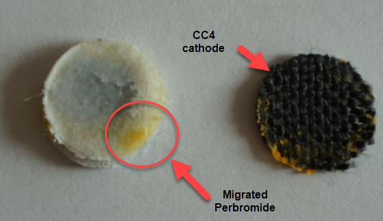
However, the solubility of TMPhABr is too low for this and what happens is that the cathode mainly generates elemental Bromine, which then flows through the battery and is converted – outside the cathode – into TMPhABr3 as it reaches the TMPhABr solid layers. What happens is that the perbromide is fixed outside the cathode, and only the portion that is in contact with the cathode is ever able to be reduced to contribute to the battery current during the discharge phase while the part that is far away from the cathode becomes “dead capacity” and is never able to be regenerated again.
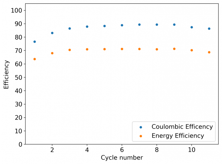
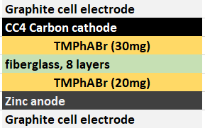
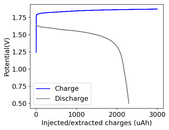
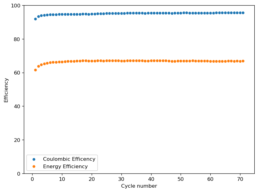
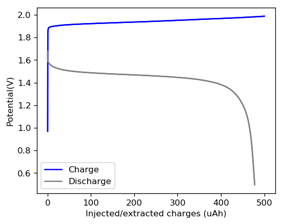
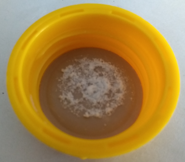
This is evident by looking at disassembled batteries – see image above – where the yellow/orange perbromide is present across the battery separator, showing that elemental bromine was produced, migrated, reacted with the organic ammonium salt to form the perbromide and was then unable to be recovered because of its distance from the cathode. This is also showed by the loss in both energy and Coulombic efficiencies for batteries that use this solid layer at higher ZnBr2 concentrations, compared with the cells that used fully dissolved ZnBr2 0.5M + TMPhABr 0.25M. The Coulombic efficiency drops from >95% to <80% while the energy efficiency drops from >80% to <70%.
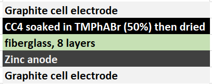
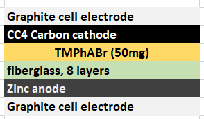
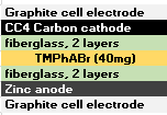
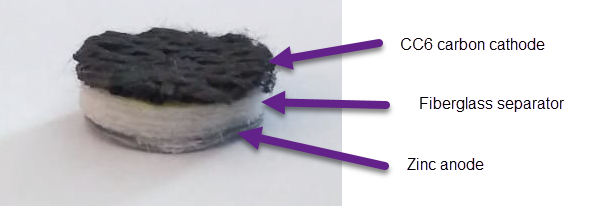
The best way to implement this solid TMPhABr strategy might actually be to introduce this solid within the structure of the cathode material (see proposed structure above). For this I have prepared a 50% w/v solution of TMPhABr (it is extremely soluble in distilled water), immersed two CC4 cathodes into it and I am now waiting for these to dry. Once they are dry I will be able to place them within batteries and run an experiment – without any solid layer – to see if this actually improves the results.