During this past week I have been experimenting and thinking more about Zn-Br batteries and how a real practical battery would look like (how it would be built and what its characteristics would be like). Let’s imagine we have found a complexing agent that can be used in highly concentrated ZnBr2 solutions. What would a prototype battery look like and how much would it cost?
The first thing we need to consider is the geometry to build such a battery. Single-cell batteries for Zn-Br chemistry are impractical due to the limits that would impose on current density – and it’s not the 19th century – so the ideal battery would probably follow a configuration similar to modern lead-acid batteries, where multiple cells are put together to achieve better results. The simplest way to do this is to stack materials next to each other within a box, then flood the box with the desired electrolyte solution.
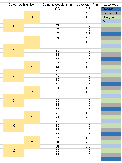
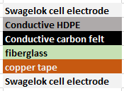
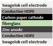
In a 101mm x 54mm x 44mm project box you could fit a volume of around 237mL. If we decide to use a very porous carbon felt electrode – which I have experience with – with titanium current collectors, glass fiber separators and zinc anodes, we would create a cell configuration like the one showed above. This would occupy the entire cell with either separator, current collector, anode or cathode material. Given that the materials used take little real volume, as they are either very porous or very thin, I’m going to assume the solution volume we will fit will be equal to 200mL, which is realistic given the characteristics of the materials.
If we use a 2M ZnBr2 solution, this would give a maximum theoretical energy of 40Wh. If the cells are all connected in parallel, this would give us a battery with a voltage of 1.85 at a capacity of 21.6 Ah. The battery would be charged at a constant current of around 2.85A, although depending on the actual kinetics this might need to go down to even 285mA. In the above design you actually have only 6 cells that are each equal to 2 normal cells connected in parallel – as they share a current collector in the cathode – so connecting these 6 in series would give you a voltage of 11.1V with an expected charging current of 475mA.
The main caveat of the above design is that it uses a 2M ZnBr2 solution, assuming we can find a complexing agent that forms an insoluble perbromide that can be in the initial formulation at a concentration equal to at least the same as the ZnBr2 then this should be no problem. After a lot of research about the solubility of perbromides and organic ammonium salts I believe this might be possible using trimethylphenylammonium bromide, but such a complexing agent has never been tried! The 200 mL of solution used here would use 90.07g of ZnBr2 and 86.45g of TMPB.
Note that this configuration would certainly not work without a complexing agent that precipitates the tribromide formed. Without it the bromine would pool at the bottom and discharge the cell – in a horizontal configuration – or just sink and discharge the cell in a vertical configuration.
| Cost (USD) | Item | URL |
| 3 | Project box | https://www.allelectronics.com/item/mb-132/abs-project-box-3.97-x-2.12-x-1.72/1.html |
| 45 | Carbon felt | https://www.ceramaterials.com/product/gfe-1-pan-graphite-felt/ |
| 10.99 | Fiberglass tissue | https://www.amazon.com/Multipurpose-Fiberglass-reinforcing-waterproofing-membranes/dp/B0719KWMJ7/ref=sr_1_5?dchild=1&keywords=fiberglass+paper&qid=1600038562&sr=8-5 |
| 11.49 | High purity Zn | https://www.amazon.com/99-9-Sheet-Plate-Metal-140x140mm/dp/B086FGDW83/ref=sr_1_5?dchild=1&keywords=Zn+sheet&qid=1600038696&sr=8-5 |
| 9.01 | Zinc Bromide | Price with shipping confirmed from Alibaba vendor |
| 19.99 | Titanium foil | https://www.amazon.com/0-3mm-200mm-300mm-Titanium-Purity/dp/B07G8YYPFV/ref=sr_1_2?dchild=1&keywords=titanium+foil&qid=1600040029&sr=8-2 |
| 18.85 | TMPB | Price with shipping confirmed from Alibaba vendor |
Using all the materials above, the cost of building such a prototype would be in the order of probably 120 USD. Probably around 200 USD after you add shipping for everything. In reality this cell is also unlikely to yield 40Wh and will most likely be in the vicinity of 20Wh if everything works as expected.
It is also important to note that an ABS project box like the one above is a risky first-choice, given that ABS can adversely react with elemental bromine, so a PTFE project box would – although much more expensive – be a safer choice for a prototype. By the time I build something like this, I hope I have already established that TMPB forms insoluble enough perbromide salts under my much more controlled Swagelok cell conditions.
Note that I am still far away from executing something like this! Currently I am even far away from testing a TMPB cell, but I wanted to write this blog post to condense all this theoretical research and serve as a referring point for me or others in the future.