Author Archives: danielfp

Zinc Bromine Batteries: First success!

In my first article about zinc-bromine batteries I discussed why these batteries are gaining interest and how some recent articles point to their potential use as reliable and cheap batteries, especially for large scale applications. After building my own DIY potentiostat/galvanostat, I wanted to use this technology to characterize home-made zinc-bromine batteries and experiment with their chemistry.

One of my initial attempts at a Zn-Bromine battery using carbon felt electrodes as both anode and cathode. Trying to charge the battery at 1mA/cm^2 never got above 1.32V and potential declined after time.

My previous article also mentioned some of my first attempts at building these batteries, which were mostly failed attempts due to the complexity of the battery builds. Even though I was able charge the batteries a little bit – and obtained relatively high Coulombic efficiencies when injecting a small amount of charge – I was never able to sustain potential values close to the expected 1.6-1.8V of the zinc bromine system. Always topping up at around 1.3-1.35V as shown in the image above, when trying to inject charges at 1mA/cm^2.

A huge problem of my first set of designs was a complete inability to adequately reproduce my batteries. The electrode construction was very complicated and every battery I tried had slightly different geometry and different amounts of electrolyte within their construction. In order to standardize the study I decided to change to a Swagelok cell construction (which I bought from China here). I bought a cell and got it delivered to the US within one week.

Button Cell Swagelok-Type Cell for Cell Testing
These are the Swagelok cells I am using to build my batteries now. These cells have an inner diameter of half an inch.

Although the Swagelok were supposed to make things easier, I started to face issues with the electrode material of the cells being reactive towards the bromine generated within the battery charging process. In my initial attempts using a carbon felt electrodes and a fiberglass separator, the stainless steel electrodes in the cell – which are inevitably exposed to the solution – were getting corroded away by the generated bromine and tribromine salts.

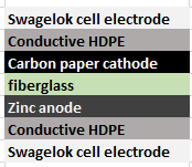
I was finally able to surmount these issues by covering the Swagelok cell electrode pieces with conductive HDPE, basically by wrapping the electrode with it and then inserting it within the Swagelok cell. Using this method I was able to produce my first successful Zn-Br cell using a tetrabutylammonium bromide (TBAB)/ZnBr2 solution (0.25 and 0.5M respectively) , a copper electrode for zinc reduction a fiber-glass separator and a carbon felt electrode for the tribromide depositing.

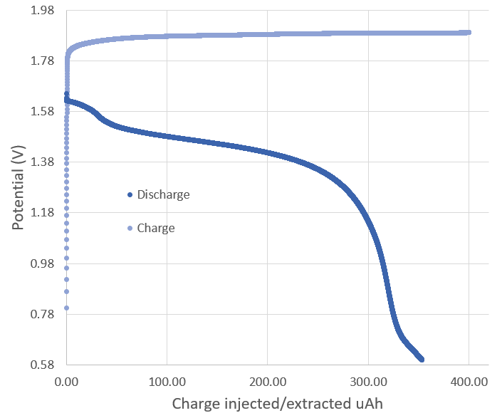
Charge/discharge curve of my first successful cell. I charged the cell to 500uAh and then discharged it until it reached 0.5V. This process was carried out at 1mA.

The image above shows you my first successful charge/discharge curve. To the best of my knowledge, this is the only example available online for experimental data of a TBAB/ZnBr2 cell. The Coulombic efficiency of the above cell was 96%, which is great considering this is the first successful one I have built. The cell used around 80-100uL of solution and 4 layers of fiber-glass separator (see my previous post for links to these materials).

I am still facing some issues related with the cutting of the separator/electrode materials to place within the cell (I have bought a 0.5 inch cutter which should make this way easier) and I am also going to try using a zinc electrode for the zinc plating, which should make things easier. I also want to see if I can get a better non-reactive conductive coating for the cell electrodes, since the conductive HDPE I am using has a quite significant resistance. Things are looking up though!

Zinc Bromine Batteries: A view and way forward

Zinc bromine batteries are a very interesting battery chemistry that goes back at least a hundred years (see here). These batteries are quite especial in that the battery is assembled in a completely discharged state, where both electrodes in the battery are relatively inert and all the charging of the battery is done by reducing/oxidizing materials in the liquid electrolyte into the electrodes. These batteries have the potential of high capacities with the use of very cheap materials, while having a safety profile significantly better than that of regular lead acid or lithium ion.

The battery reduces (plates) zinc into the negative electrode of the battery and oxidizes bromide to elemental bromine in the positive electrode of the battery. These reactions allow the battery to have a relatively high theoretical potential but also implies that you get elemental bromine – a highly reactive liquid – in the anode of the battery. This is one of the main complications and reasons why these batteries have never been very successful in commercial applications. The bromine is not entirely insoluble in the electrolyte – which is generally water – and can therefore migrate to the negative telectrode to react with the zinc, causing a self-discharging of the battery that is extremely detrimental to long term storage in these systems.

The minimum architecture Zn-Br battery built by Princeton

The above is why these systems have mostly been exploited as flow-batteries, because if you can take the bromine produced and just move it away from the zinc deposit, you can effectively ensure that the battery charge is preserved as a function of time. This inevitably complicates battery construction substantially, but does allow for some practical applications of the technology.

During the past few years there has been a renewed interest in this technology, first due to some Princeton articles that talked about these batteries in the context of a “minimum architecture” battery (see here) but this actually just reproduced some of the earlier results of this technology and does not provide substantial solutions to the problems associated with self-discharge in these systems. They however point to the fact that these problems can actually be relatively inconsequential if the batteries are used for mass storage and the actual time the energy needs to be stored for is low. The fact of the matter is that the self-discharge reaction in these batteries is not destructive for the battery, just a waste of energy, contrary to other battery chemistries where self-discharge can generate problematic issues that kill the batteries themselves. The point being, if you need to store the energy for a short time and you can waste some, this is your chemistry.

However some people realized that the problem of self-discharge could be reduced substantially by using some substances that capture the Bromine produced into insoluble tribromide salts. This is what some smart people from China did (see here) using TPA (tetrapropylammonium bromide). The introduction of this chemical into the battery chemistry allows tetrapropylammonium tribromide to form in the positive electrode of the battery – instead of liquid bromine – which substantially prevents the reaction with the zinc on the other electrode as these salt is significantly more insoluble than the bromine.

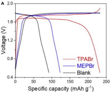
Some results of the Chinese paper mentioned above, which was published in July 2020.

The image above, which contains some of the results in their paper, shows that Zn-Br technology, when used in this manner, has the potential to have specific energy and power values that can rival even modern lithium ion technology. Furthermore, the cost of all of the materials involved here is relatively low, although these Chinese experiments did use a fancier carbon electron for their positive electrode.

Looking at what the Chinese did, I wondered if it would be possible to create a battery that reproduces their results, with some materials I could find online. I found a carbon felt from ceramaterials with high conductivity and surface area, you can buy an A4 sized sample for less than 50 USD and coupled this with some conductive HDPE, a copper mesh and copper tape. Since zinc can be plated onto carbon felt as well (see here) I decided to go with a construction mechanism where both of my battery electrodes will be constructed from the same material. For the separator I decided to go with a fiberglass separator, the best one I could find for the purpose was this tissue. In order to enclose the battery I decided to go with some shrink tubing, since I could easily seal the ends with a little bit of heat.

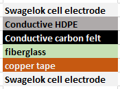
You can see my fully assembled 1 cm squared electrodes. I left a bit uncovered on the one to the left so that you can see all the layers.

The electrodes are made by heat pressing HDPE to the carbon felt using a regular iron (with some wax paper to prevent it from sticking to the iron) then heat pressing the copper mesh onto the HDPE, then putting the copper tape on the mesh and finally pressing another layer of HDPE to seal all the components in. The resistance measured between the copper and the felt in these electrodes should be lower than 1 ohm, meaning you should be easily able to measure continuity between them.

To build a battery two of these electrodes are put together with 4 layers of the fiber glass between them – it’s pretty large pore so using 1 or 2 layers often caused shorting issues between the carbon felt electrodes – and then placing that inside the shrink tubing. I then sealed the sides of the tubing using a regular iron to ensure everything was enclosed.

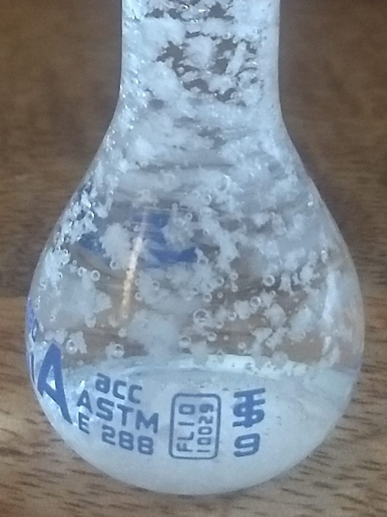
The next step is to prepare the solution, for which I used a class A 10mL volumetric flask and prepared a 0.5M solution of Zinc Bromide and tetrabutylammonium bromide (TBAB). Notice that I used tetrabutyl, not tetrapropyl, since this is more readily available. Both of these substances were bought on ebay or amazon, although they are more expensive than they would if you bought them in bulk quantities. The solution is then injected into the tubing using a needle and the hole is then sealed using regular electrical tape (usually I open to holes to allow air to go out of one). The above solution had some solubility problems (the TBAB wouldn’t go into solution at this concentration) so some of my future experiments will test out different concentrations.

Finished battery
Cross-section of a battery cut through the middle after assembly

I have already started testing some of these batteries and look forward to sharing some of their actual electrochemical results within a future post. As a sneak peak I can tell you that the coulombic efficiency of these cells is greater than 92%. But you will see much more, including charge/discharge curves and other tests, really soon!

Building a DIY opensource USB potentiostat/galvanostat: Part Three

Through the past month, I have been trying to build an open source potetionstat/galvanostat as described in a research paper (see here). Knowing that the probability of failure trying to manually solder such small components was high, I ordered some fully assembled PCBs from PCBway one month ago to make sure I had a plan B in case my manual attempts failed.

This is the Chinese made potentiostat-galvanostat board built by PCBway using the files I provided (which are files obtained/modified from the paper mentioned before).

If you have read my last few posts, this is exactly what happened, I completely failed at successfully assembling this board myself (not the best soldering hand in town!) but thankfully received my fully assembled PCB from China a couple of days ago. The PCB from china worked flawlessly, allowing me to perform the calibration and have a fully functioning potentiostat/galvanostat for home use.

The python software provided by the creators of this potentiostat also worked really well. Using the knowledge I obtained within the last couple of posts, I was able to easily use the drivers provided by the authors to use this software without any issues. The software implements some basic experiments, like CV, charge/discharge curves and Rate testing, but the best thing is that the entire thing is open source, allowing me to customize the experiments to do whatever I want, something I know many researchers wish they could do with the expensive software packages – all closed source – provided by normal potetionstat manufacturers.

These are some charge/discharge curves I am now measuring for a prototytpe battery I made. I modified the software in order to be able to do the charge to 350 uAh, then proceed with the discharge.

This ends my quest for the building of a – now not so much – DIY potentiostat/galvanostat, giving me the functionality of a piece of equipment that usually costs around 1000-3000 USD for just a couple of hundred dollars. Even more, this potentiostat allows me to use current in the -25 to 25 mA range, something that isn’t that common unless you go for the more expensive potentiostats above the 3K+ USD range, since the cheapest potentiostats are usually built for high sensitivity at lower currents – because these are mostly intended for analytical chemistry experiments – rather than for the charging/discharging of battery cells.

My posts will now move onto the experimental batteries I am attempting to build and their characterization. I have always noticed that DIY batteries on the internet are almost never properly characterized – no wonder given how difficult it has been up until now to get access to proper equipment to do so – but with this piece of hardware I will now be able to perform all of these experiments without issues.

Building a DIY opensource USB potentiostat/galvanostat: Part Two

With some improved soldering skills I reattempted soldering of all the components into the brand new PCB I had left from Osha Park. After doing this I still experienced a significant amount of shorts but this time I was able to pinpoint the sources by some smoke coming off the PCB (not the greatest sign!). In the end all the shorts were coming from what seems to be the underside of the microchips, probably related with some flux residue that got carbonized and became somewhat conductive after the chips were soldered and the circuit was powered.

My somewhat successfully powered DIY potentiostat/galvanostat

With this information I now resoldered all the chips, being very careful about cleaning all the flux to ensure that there were not shorts after the chip was put into place. With all these shorts removed I was able to finally power the board without any excessive current drain.

Due to the fact that the drivers that come with this device are unsigned I had to restart windows using the “Advanced boot options” to ensure that driver signing was disabled. Also remember to install pyusb and usblib before launching the python program.

With this done I was able to successfully connect the PCB to the computer and use the software to interact with it. However after trying to do the calibration I noticed that the entire potentiostat/galvanostat functionality was actually not working and I was actually unable to set any potential without the circuit going a bit “crazy”. As you can see in the image below, everytime I tried to set the potential to some value I just got some random potential being set, with current bouncing all over the place.

Trying to set the potential of the device to 1.5V with RE connected to WE and CE connected to SE just generated a bunch of noise

Feeling the temperature of the different chips, the one that is overheating seems to be the OPA4192 chip. I tried to remove it and resolder it again, but I have the same problems and the same type of abnormal behavior. Right now it seems that the most likely scenario is that all my desoldering and soldering endeavors have fried one of the components of the board, meaning that I might not be able to get it to work at all with the current components.

Thankfully plan B is still going on – a PCB being fully assembled by pcbway – so I should be able to get a fully working board within the next couple of weeks. I am still debating whether it’s worth it to order new components and try on a new board – with my already gained experienced – but I think I’ll wait for the working PCB to ensure this board works as I expect it to before I make any further DIY attempts.

Building a DIY opensource USB potentiostat/galvanostat: Part One

As I explained on my last post, I want to build a system to characterize batteries at a small scale at my home. This means being able to test things like their coulombic efficiency and measure things like charge/discharge curves. The perfect solution came as the USB potentiostat/galvanostat published in this paper so I order 3 boards using Oshapark and got the rest of the parts from microchipdirect and digikey.

PCB board I received from Oshapark

I received my PCB order last week – as shown above – and proceeded to solder the components that I received as well. After soldering all the components I then connected the board to the PicKit3 programmer using the programming leads. By the way, the square pin right below the K3 mark should match pin 1 in the programmer, something that is not mentioned within the above cited paper.

When I did this I used the MPLAB X IPE v5.4 software, downloaded from this link. Using the advanced options I made the PicKit3 provide power to the board and I then proceeded to program it at 4V because when I connected it at 5V I received some erros about VDD not matching between the microcontroller voltage and the provided voltage. In the end I was able to program and verify the chip at this voltage with the hex file provided by the authors of the paper.

After this I then connected the chip into the computer using a USB port and instantly received a USB overcurrent warning, which immediately disconnected the PCB from my computer (uh oh). After checking the board I noticed a short after the charge pumping circuit, where the +9V line was almost shorted to ground, with a resistance of around 10-100 ohm when it should be at least 10kohm given the lowest resistance connected between ground and this line (R2). You can test this by measuring resistance between the leads in R2.

After painfully taking out all the components one-by-one from one PCB and soldering them onto a second one I realized that my problem was that overheating the PCB actually created a short-to-ground in this line, more likely than not related with partial melting of the PCB in the U8 microchip leads where the +9V and ground lines are particularly close to one another. This can actually happen by heating anywhere on the board that’s connected to the ground line, even if you overheat something like the LED D3 or D4 lines. I noticed because I caused the same damage on the second board I was working on, even though the lines were not shorted right before I was working on the D4 LED but became shorted right after I spent around 20 seconds applying heat (yes, my bad).

Two boards I worked on that are now useless. Left one was the first I soldered all components on, second is the one I was testing components on when I noticed the short caused by over-heating the ground line.

Right now I sadly only have one board left (sigh) and have already desoldered and soldered a lot of the components. I now need to desolder all the remaining components from these two boards solder them onto the third board, although this case I will need to be especially careful about how I apply heat to the board as I definitely do not want to cause this shorting issue again. I will update this blog after I try again.