Through the past month, I have been trying to build an open source potetionstat/galvanostat as described in a research paper (see here). Knowing that the probability of failure trying to manually solder such small components was high, I ordered some fully assembled PCBs from PCBway one month ago to make sure I had a plan B in case my manual attempts failed.
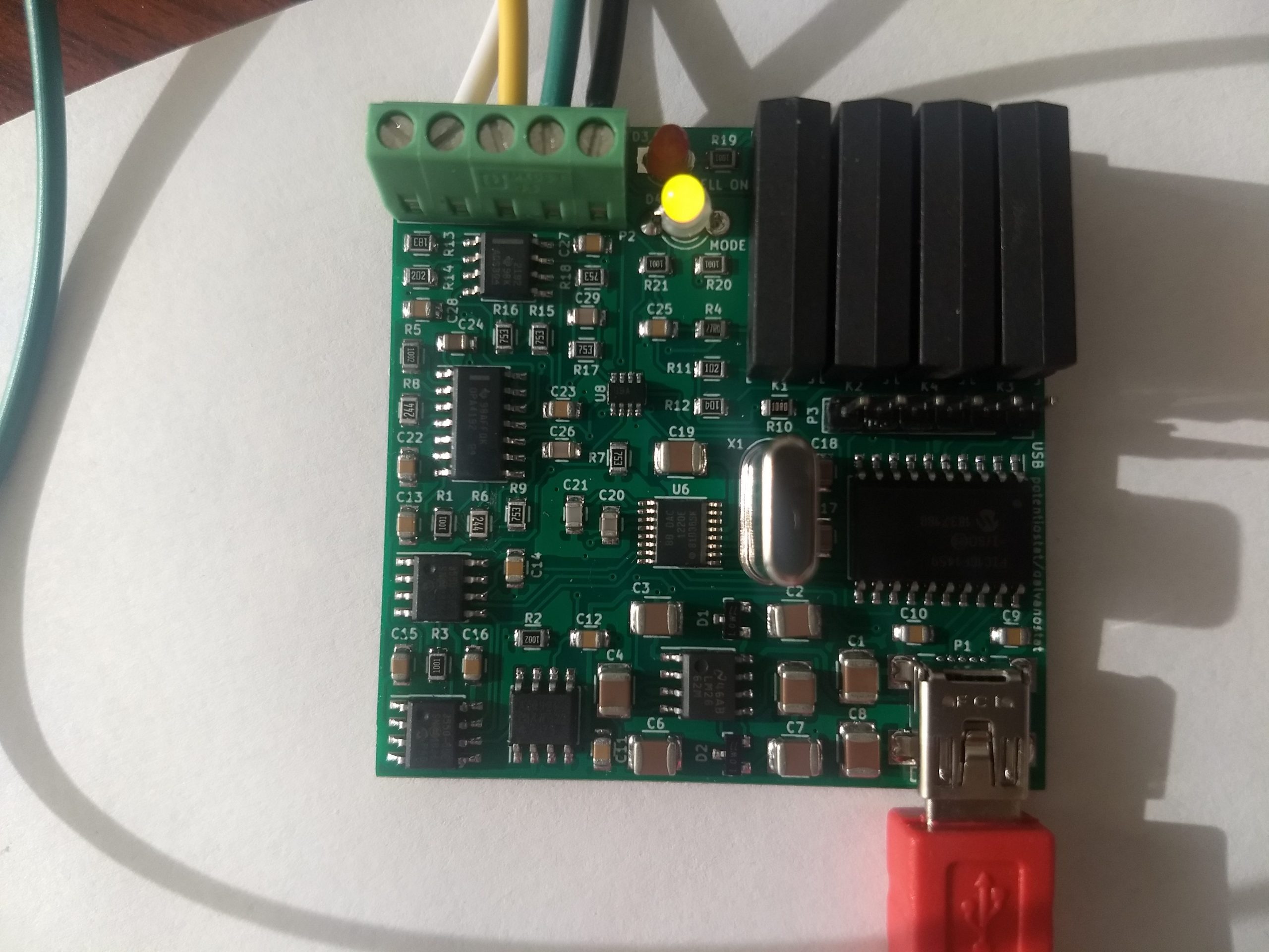
If you have read my last few posts, this is exactly what happened, I completely failed at successfully assembling this board myself (not the best soldering hand in town!) but thankfully received my fully assembled PCB from China a couple of days ago. The PCB from china worked flawlessly, allowing me to perform the calibration and have a fully functioning potentiostat/galvanostat for home use.
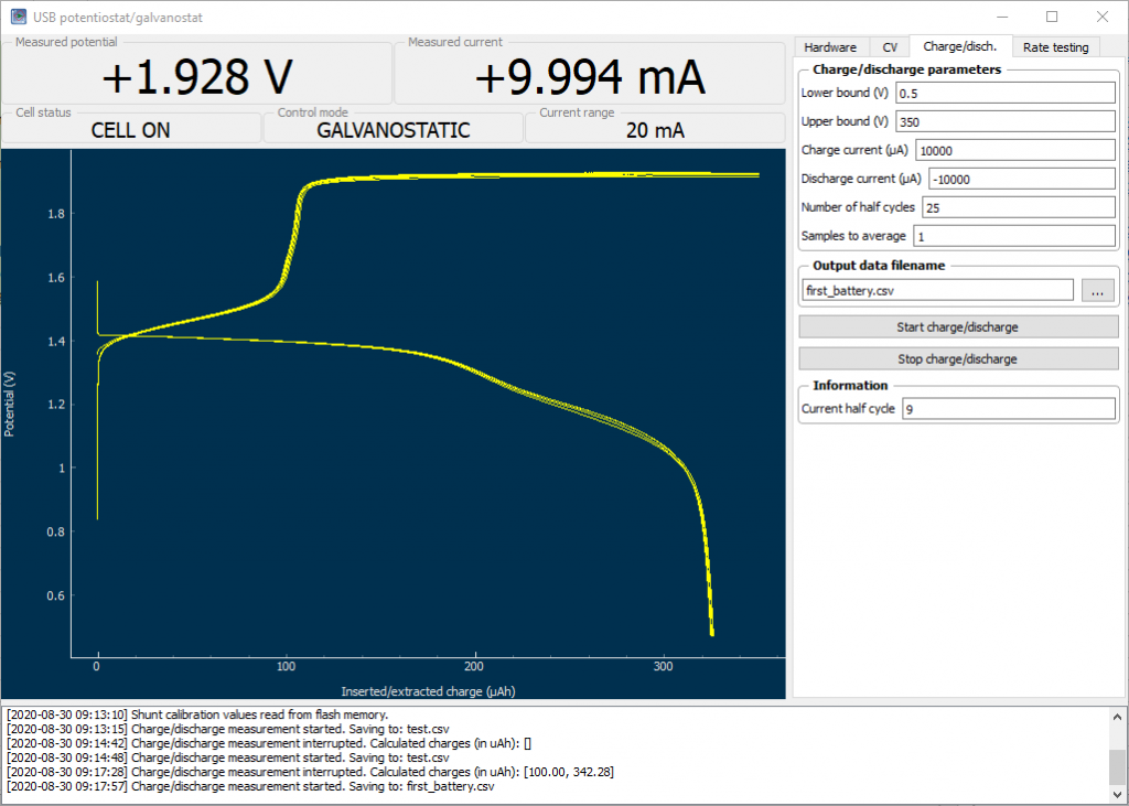
The python software provided by the creators of this potentiostat also worked really well. Using the knowledge I obtained within the last couple of posts, I was able to easily use the drivers provided by the authors to use this software without any issues. The software implements some basic experiments, like CV, charge/discharge curves and Rate testing, but the best thing is that the entire thing is open source, allowing me to customize the experiments to do whatever I want, something I know many researchers wish they could do with the expensive software packages – all closed source – provided by normal potetionstat manufacturers.
This ends my quest for the building of a – now not so much – DIY potentiostat/galvanostat, giving me the functionality of a piece of equipment that usually costs around 1000-3000 USD for just a couple of hundred dollars. Even more, this potentiostat allows me to use current in the -25 to 25 mA range, something that isn’t that common unless you go for the more expensive potentiostats above the 3K+ USD range, since the cheapest potentiostats are usually built for high sensitivity at lower currents – because these are mostly intended for analytical chemistry experiments – rather than for the charging/discharging of battery cells.
My posts will now move onto the experimental batteries I am attempting to build and their characterization. I have always noticed that DIY batteries on the internet are almost never properly characterized – no wonder given how difficult it has been up until now to get access to proper equipment to do so – but with this piece of hardware I will now be able to perform all of these experiments without issues.
Pingback: Zinc Bromine Batteries: First success! – Chemisting
Hi,
I am very interested in this topic.
1) It is possible to use this item to control the value of and working electrode
against another one ( counter electrode)?
2) how much energy this potentiostat consume?
3) How to purchase this potentiostat?
With my best regards
Koffi
Hi Koffi,
To answer your questions:
1) Yes, it can act as both potentiostat and galvanostat.
2) As a potentiostat, probably not much since very little current is drawn. The max power the potentiostat could ever consume is limited by the USB port at around 2.5W but as a potentiostat it consumes probably 20-100mW under normal use.
3) It is not sold anywhere, you need to build it yourself or have it made for you by a company that does electronic circuit assembly.
I hope this helps,
Daniel
Hi Daniel,
How have you found this board working over the several months that you have used it now? I am thinking of getting one like you did (my soldering skills are probably much worse so PCBWay will have to assist me).
Yusuf
Hi Yusuf,
Thanks for writing. Yes, it has worked great for me. However do bear in mind that this board is limited to +/- 25mA of current, so you will only be able to characterize relatively small batteries. Great for small scale research though. Let me know if you have other questions,
Daniel
hi there,
Wonderful project!
Have you a file with board/bom etc available that you might be willing to share?
Perhaps you have a website or github listing for it?
Thanks again for sharing this.
Doug
Thanks for commenting. I used the files available in the cited paper. https://www.sciencedirect.com/science/article/pii/S2468067217300317
Hi danielfp,
Really appriciate your work,
I am Steve from Vietnam
I am developing another version from yours.
There are se questions:
– can we change Pic16f1xx to Atmega328p ?this make coding easier for many people and it has i2c interface which allows to attach EIS module.
– your recent version is with 200mA update, however the cost is significant. I have another solution which create a booster module separately. Of course, it may will make some delay in signal. But for battery / supercapacitor measurement it seems acceptable, for sensor application, the original version is exceptional .
Looking forward to your comment,
Thanks for commenting Steve! I didn’t design or modify this circuit. I used the design from the cited article as-is.
Hi danielfp,
sorry for having another maybe dumb question. I finally got the potentiostat and put on the firmware via a PICKit3. When I start the python software I can connect to my potentiostat and it gives me a live view of the current and the voltage. I can turn on and off the manual cell connection (indicated by the LED) and switch between potentiostatic and galvanostatic (indicated by the other LED). Unfortunately when I set a potential or a current nothing changes in the measured potential or current. Am I missing anything or how did your first experiment setup look. So far only some copper cables are attached to the potetiostat.
Thank you
Michi
Hi danielfp,
cool project. I’m also planning to get the potentiostat. But I’m still struggling to place the order at PCBway. I got the files from your cited paper (https://www.sciencedirect.com/science/article/pii/S2468067217300317). Somehow PCBway needs a BOM file.
Could you show how your proper order looked like?
Thanks
Thanks for commenting Michi. The paper also includes a bill of materials. I only used the materials within the paper to make the order at PCBway.
Thanks.
So in total PCBway only needs the gerber files and the BOM file, if I understood it correctly?
Yea, that’s all I had to provide.
Thank you. I’ll give it a go.
Hi danielfp,
it’s me Michi again. I somehow cannot manage to set the voltage correctly. It always stays at the same value in the GUI, even though I set a different value in the python program. Do you have to set up a experiment with a reference cell or how did it work for you? How does a working experiment for you look?
Thanks in advance
Michi
Hi Michael,
You can refer to the paper introducing the software and the potentiostat for more information about basic experiments to run and how to test the device. Make sure you run the basic calibration procedures suggested before trying to perform any experiments. As a basic experiment you can connect the device to a 10K ohm resistor and set different currents or potentials, you can also run a CV curve on it. Using a capacitor you can also perform basic charge/discharge experiments. As I mentioned it is likely better to refer to the paper describing this device for more information about how to properly use it. A basic understanding about electronics and potentiostats is required to properly use this. I hope this helps,
Best Regards,
Daniel Fernandez Ph.D.
Dear Daniel,
Thank you for sharing your project.
I have just contacted PCBway to order, sent them the gerber files and tdstatv3.csv (is this the BOM?).
As I am referring my order to your previous order, is there chance you are still keeping the order number (something starts with W)?
Kind regards,
Egan
You can see my order details here (https://diysolarforum.com/attachments/1621455659007-png.49650/)
Pingback: A home setup for cyclic voltammetry | Chemisting
Pingback: New and improved DIY potentiostat/galvanostat for battery charge/discharge cycling | Chemisting