Tag Archives: batteries

Zinc Bromine Batteries: First success!

In my first article about zinc-bromine batteries I discussed why these batteries are gaining interest and how some recent articles point to their potential use as reliable and cheap batteries, especially for large scale applications. After building my own DIY potentiostat/galvanostat, I wanted to use this technology to characterize home-made zinc-bromine batteries and experiment with their chemistry.

One of my initial attempts at a Zn-Bromine battery using carbon felt electrodes as both anode and cathode. Trying to charge the battery at 1mA/cm^2 never got above 1.32V and potential declined after time.

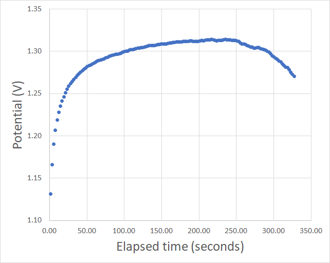
My previous article also mentioned some of my first attempts at building these batteries, which were mostly failed attempts due to the complexity of the battery builds. Even though I was able charge the batteries a little bit – and obtained relatively high Coulombic efficiencies when injecting a small amount of charge – I was never able to sustain potential values close to the expected 1.6-1.8V of the zinc bromine system. Always topping up at around 1.3-1.35V as shown in the image above, when trying to inject charges at 1mA/cm^2.

A huge problem of my first set of designs was a complete inability to adequately reproduce my batteries. The electrode construction was very complicated and every battery I tried had slightly different geometry and different amounts of electrolyte within their construction. In order to standardize the study I decided to change to a Swagelok cell construction (which I bought from China here). I bought a cell and got it delivered to the US within one week.

Button Cell Swagelok-Type Cell for Cell Testing
These are the Swagelok cells I am using to build my batteries now. These cells have an inner diameter of half an inch.

Although the Swagelok were supposed to make things easier, I started to face issues with the electrode material of the cells being reactive towards the bromine generated within the battery charging process. In my initial attempts using a carbon felt electrodes and a fiberglass separator, the stainless steel electrodes in the cell – which are inevitably exposed to the solution – were getting corroded away by the generated bromine and tribromine salts.

I was finally able to surmount these issues by covering the Swagelok cell electrode pieces with conductive HDPE, basically by wrapping the electrode with it and then inserting it within the Swagelok cell. Using this method I was able to produce my first successful Zn-Br cell using a tetrabutylammonium bromide (TBAB)/ZnBr2 solution (0.25 and 0.5M respectively) , a copper electrode for zinc reduction a fiber-glass separator and a carbon felt electrode for the tribromide depositing.

Charge/discharge curve of my first successful cell. I charged the cell to 500uAh and then discharged it until it reached 0.5V. This process was carried out at 1mA.

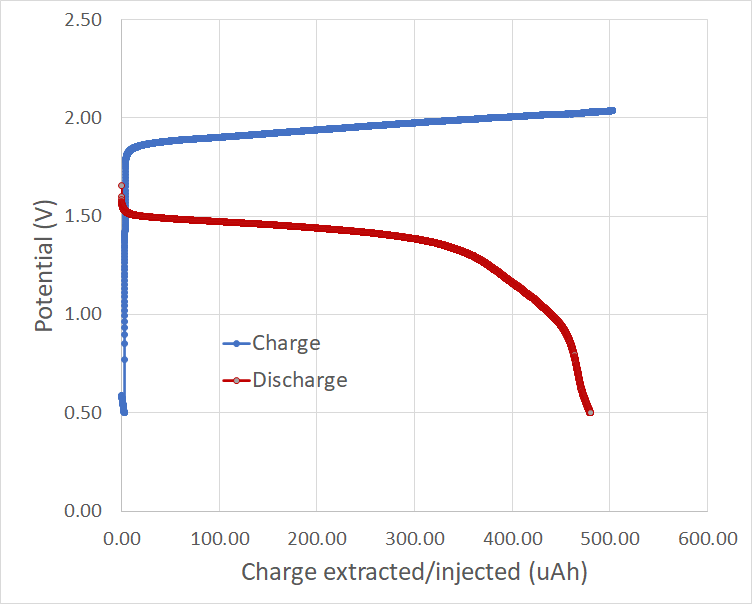
The image above shows you my first successful charge/discharge curve. To the best of my knowledge, this is the only example available online for experimental data of a TBAB/ZnBr2 cell. The Coulombic efficiency of the above cell was 96%, which is great considering this is the first successful one I have built. The cell used around 80-100uL of solution and 4 layers of fiber-glass separator (see my previous post for links to these materials).

I am still facing some issues related with the cutting of the separator/electrode materials to place within the cell (I have bought a 0.5 inch cutter which should make this way easier) and I am also going to try using a zinc electrode for the zinc plating, which should make things easier. I also want to see if I can get a better non-reactive conductive coating for the cell electrodes, since the conductive HDPE I am using has a quite significant resistance. Things are looking up though!

Building a DIY opensource USB potentiostat/galvanostat: Part One

As I explained on my last post, I want to build a system to characterize batteries at a small scale at my home. This means being able to test things like their coulombic efficiency and measure things like charge/discharge curves. The perfect solution came as the USB potentiostat/galvanostat published in this paper so I order 3 boards using Oshapark and got the rest of the parts from microchipdirect and digikey.

PCB board I received from Oshapark

I received my PCB order last week – as shown above – and proceeded to solder the components that I received as well. After soldering all the components I then connected the board to the PicKit3 programmer using the programming leads. By the way, the square pin right below the K3 mark should match pin 1 in the programmer, something that is not mentioned within the above cited paper.

When I did this I used the MPLAB X IPE v5.4 software, downloaded from this link. Using the advanced options I made the PicKit3 provide power to the board and I then proceeded to program it at 4V because when I connected it at 5V I received some erros about VDD not matching between the microcontroller voltage and the provided voltage. In the end I was able to program and verify the chip at this voltage with the hex file provided by the authors of the paper.

After this I then connected the chip into the computer using a USB port and instantly received a USB overcurrent warning, which immediately disconnected the PCB from my computer (uh oh). After checking the board I noticed a short after the charge pumping circuit, where the +9V line was almost shorted to ground, with a resistance of around 10-100 ohm when it should be at least 10kohm given the lowest resistance connected between ground and this line (R2). You can test this by measuring resistance between the leads in R2.

After painfully taking out all the components one-by-one from one PCB and soldering them onto a second one I realized that my problem was that overheating the PCB actually created a short-to-ground in this line, more likely than not related with partial melting of the PCB in the U8 microchip leads where the +9V and ground lines are particularly close to one another. This can actually happen by heating anywhere on the board that’s connected to the ground line, even if you overheat something like the LED D3 or D4 lines. I noticed because I caused the same damage on the second board I was working on, even though the lines were not shorted right before I was working on the D4 LED but became shorted right after I spent around 20 seconds applying heat (yes, my bad).

Two boards I worked on that are now useless. Left one was the first I soldered all components on, second is the one I was testing components on when I noticed the short caused by over-heating the ground line.

Right now I sadly only have one board left (sigh) and have already desoldered and soldered a lot of the components. I now need to desolder all the remaining components from these two boards solder them onto the third board, although this case I will need to be especially careful about how I apply heat to the board as I definitely do not want to cause this shorting issue again. I will update this blog after I try again.

Building a machine to test and research batteries at home

As a chemist who loves electro-chemistry, battery technology has always seemed incredibly interesting, especially since it’s within the group of potential topics that could be researched with some degree of success at home. This is because batteries can be made within a very wide array of chemistries, some of which use very easy-to-find materials and the equipment necessary to research batteries at a small scale should not be hard to build.

Public PCB project at OshPark

However, after looking at a lot of people sharing their DIY batteries at their own houses on the internet, it seems clear that most of them don’t do any proper characterization of their batteries at all and those who do – who appear to be very few – seem to use relatively expensive pieces of equipment to do so, probably the lower end of what would be used within a regular university research environment.

The options available to minimally characterize batteries, which means at least measuring their charge/discharge curves seem to all be expensive and there is no commercial option I could find that would allow you to perform these tests for less than 1000 USD.

However, I did find a very interesting publication (here) where the researchers share the PCB, software, firmware and bill of materials for a cheap galvanostat/potentiostat that can be used for the characterization of small batteries. Given its limited current +/25mA, it cannot be used for the characterization of any larger batteries, but it should allow for some very interesting and well-done research of small batteries at home.

I added this PCB to OshaPark (you can order it here) and I have ordered the materials from Digikey using the bill of materials provided by the author within the paper (you can use this file to upload to dikigey directly) . The microcontroller used within this project also requires to be programmed using a PicKit3, so you will need to get one here. Note that due to COVID related supply constraints I had to order the MCP3550-50E/SN microchip from microchipdirect.com instead of digikey and I also changed the mini-USB port for a micro-USB port (609-4053-1-ND).

Current progress of my order at pcbway

As backup plan I have also ordered a fully assembled PCB board from pcbway.com, which charged me a total of 154 USD for the entire production of the PCB and mounting all the surface components. This is all done in China and the exported to the US, so it will take around a month for the entire process to go through. I want to compare the quality of my own assembly with the product I obtain from China.

In this process I also got quotes for several different US manufacturers for the production of these boards, but came to the conclusion that it is not economical unless I wanted to get at least 10-20 manufactured. This is because the price is often in the 1200-1500 USD range, independently of whether I get 1 or 10-12 boards done.

I still haven’t received everything I need from oshpark and digikey to assemble the board but once I do I will update you on my progress building/programming/testing this open source galvanostat/potentiostat.