Tag Archives: batteries

A low cost, open source, Cu/Mn rechargeable static battery

Building a rechargeable battery is not an easy task. Although many great technologies are available (like LiFePO4 or even lead acid batteries), building these batteries isn’t trivial because of the technological hurdles, manufacturing requirements, chemical substances, knowledge and safety requirements. It would be ideal if we had access to an open source rechargeable battery technology that was easy to construct in practice with readily available materials, robust and at low cost.
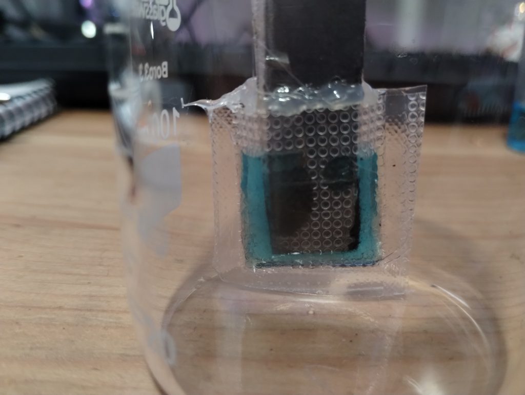
This is a sample 0.5mL cell using a copper anode and a carbon felt cathode (0.3mm). A polypropylene felt separator is used between both. The cell is 1cmx1cmx0.5cm in volume.

In a previous post I talked about Cu/Mn batteries and how several different papers describe batteries using Cu sulfate and Mn sulfate along with sulfuric acid to create robust batteries with significant capacities, even above 40Ah/L. Such batteries would be close to ideal as they are easy to build, use earth abundant materials and – in theory – are very robust. However, my efforts to reproduce these batteries were plagued with failure as I was unable to reproduce both their reversibility and their capacities.

Furthermore, this Cu/Mn technology using sulfuric acid has been patented by a French company (years before the Chinese articles started sharing the chemistry in 2017). This means that this chemistry is not open source and significant battles could arise from the use of this technology at a wide scale. This also explains why the patent applications mentioned by some of the Chinese researchers in their papers cannot be found (probably the patents were denied because of the preceding French patent).
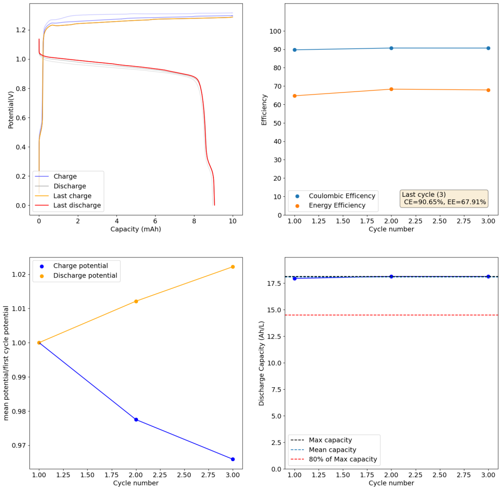
Experimental results of the Cu/Mn cell using methylsulfonic acid. The electrolyte was prepared with 0.05g of FeSO4.7H2O, 2g CuSO4.5H2O, 1.8g of MnSO4.4H2O, 2mL of 70% CH3SO3H and 8mL of RO water. Cycling was done at 5mA/cm2

To tackle my problems reproducing this chemistry, the hurdles with intellectual property and some issues dealing with the solubility limit of copper/manganese sulfate mixes, I have modified this technology to use methansulfonic acid (CH3SO3H) instead of sulfuric acid. Methanesulfonic acid is easier to get than sulfuric acid – because it has no regulatory restrictions – and the solubility of both copper and manganese mesylates is higher than that of their sulfates, meaning that even higher capacities than with sulfuric acid should be possible.

The above experimental results show cycling of the cell shown in the first picture. This chemistry achieves a CE above 90% with an EE above 65%, the cycling is also very stable with very reversible MnO2 formation in the highly acidic media. The electrolyte tested is roughly 0.8m Cu, 0.8m Mn and 1m CH3SO3H. I haven’t tried changing the acid concentration or preparing more highly concentrated electrolytes yet, as I am still fine tuning the cell fabrication process to enhance reproducibility. The cells right now can be charged to 20Ah/L, which is already an interesting level of capacity, although 40Ah/L should be possible.
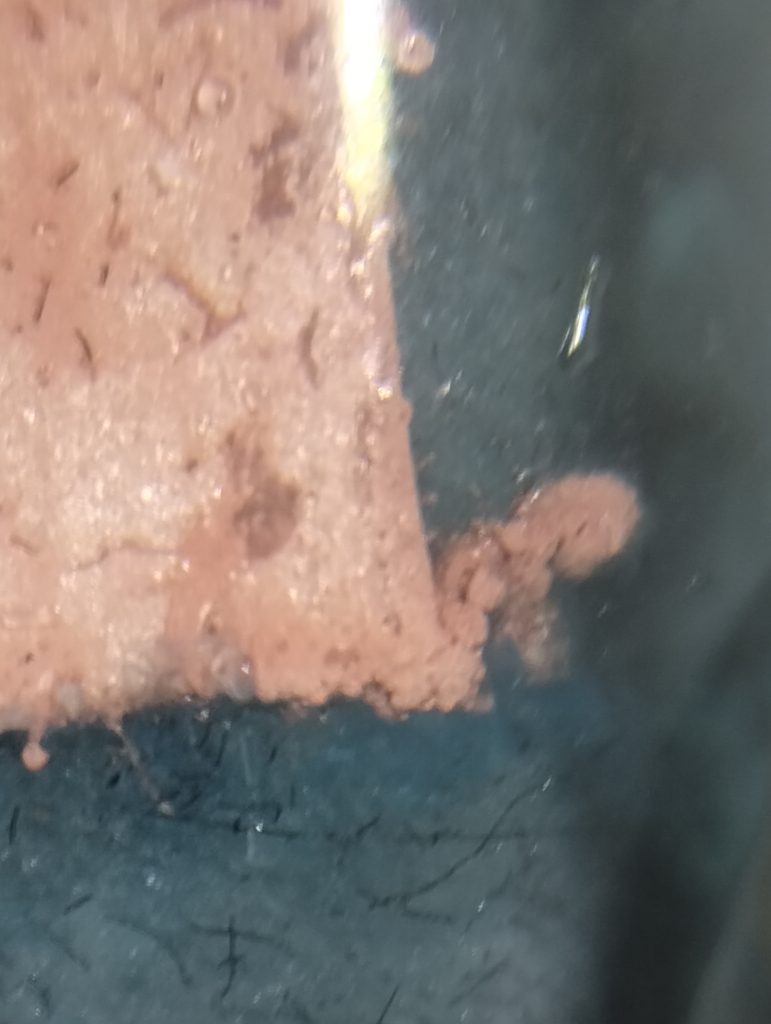
Image of dendrites due to electric field abnormalities around the edges of the Cu anode.

A very important issue I’ve noticed is that dendrites tend to appear around the edges of my Cu anodes due to electric field instabilities, as the Cu prefers to grow in the free solution rather than through the polypropylene separator. This can cause the battery to short when charging to very high capacities). Cells without separators – with just the electrodes hanging parallel as in the case of some of the Chinese papers – could help alleviate the issue. I am also trying passivating the edges using nail polish, to see if this fully solves the issue.

While the Cu/Mn battery chemistry using H2SO4 is clearly patented, the innovation using CH3SO3H is not protected, neither covered by the scope of the current patent nor previously published anywhere else (my innovation to the best of my knowledge). The publication of this blog post should ensure that this technology will remain patent-free.

Update:
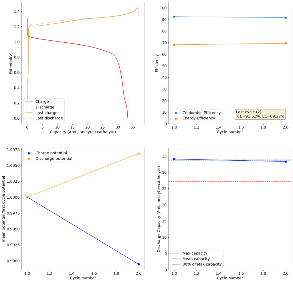
The results above show the cell being charged to 1.45V (This is likely the Nernst limit of the cell). I got a discharge capacity of 33.6Ah/L at 10mA/cm2. Electrolyte is identical to the one mentioned before. The CE and EE are still the same at higher capacity. Dendrites do not seem to get worse provided enough space is left between the edge of the copper electrode and the edge of the separator.
Zinc Bromine Batteries: What happens if you don’t use a sequestering agent?

Almost all of my efforts in the construction of Zn-Br batteries have focused on the used of sequestering agents in order to enhance the performance of the batteries and obtain higher energy densities and lower self-discharge rates. However, a couple of people have asked me what the results of a “minimal architecture” Zinc-Bromine battery would be with my current battery design. I therefore put together a battery using a 0.2mm Zn anode, 15 layers of fiberglass separator, a GFE-1 cathode without any pretreatment and a 2.7M ZnBr2 electrolyte with 1% Tween20 (which is needed to prevent dendrite formation).

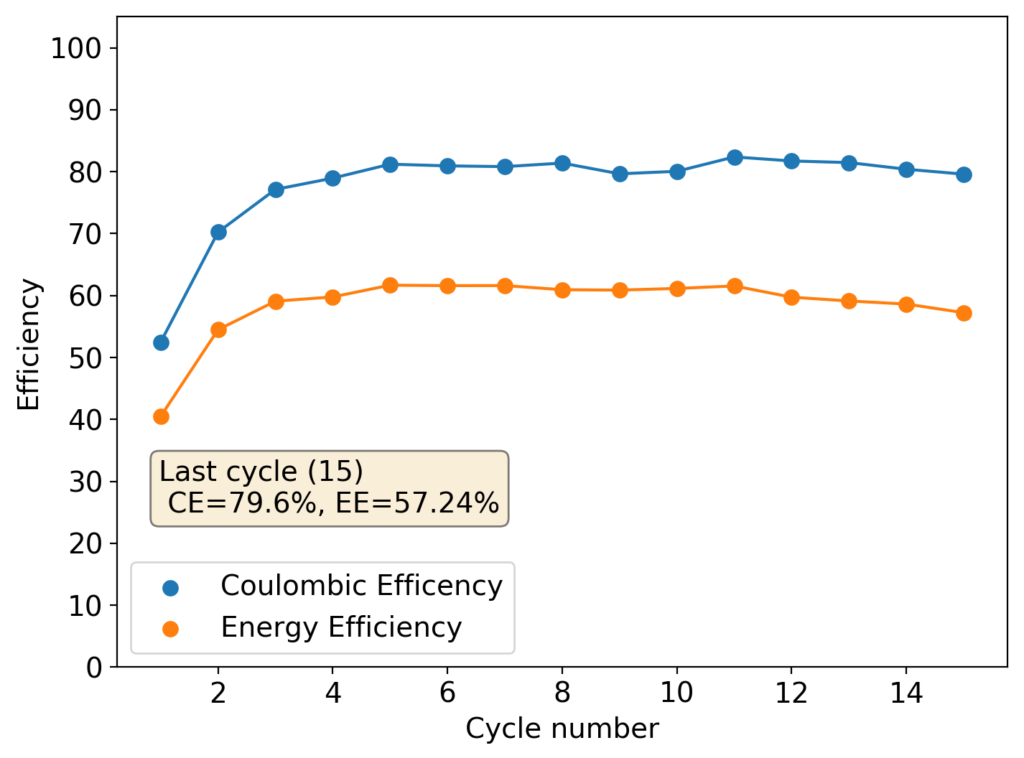
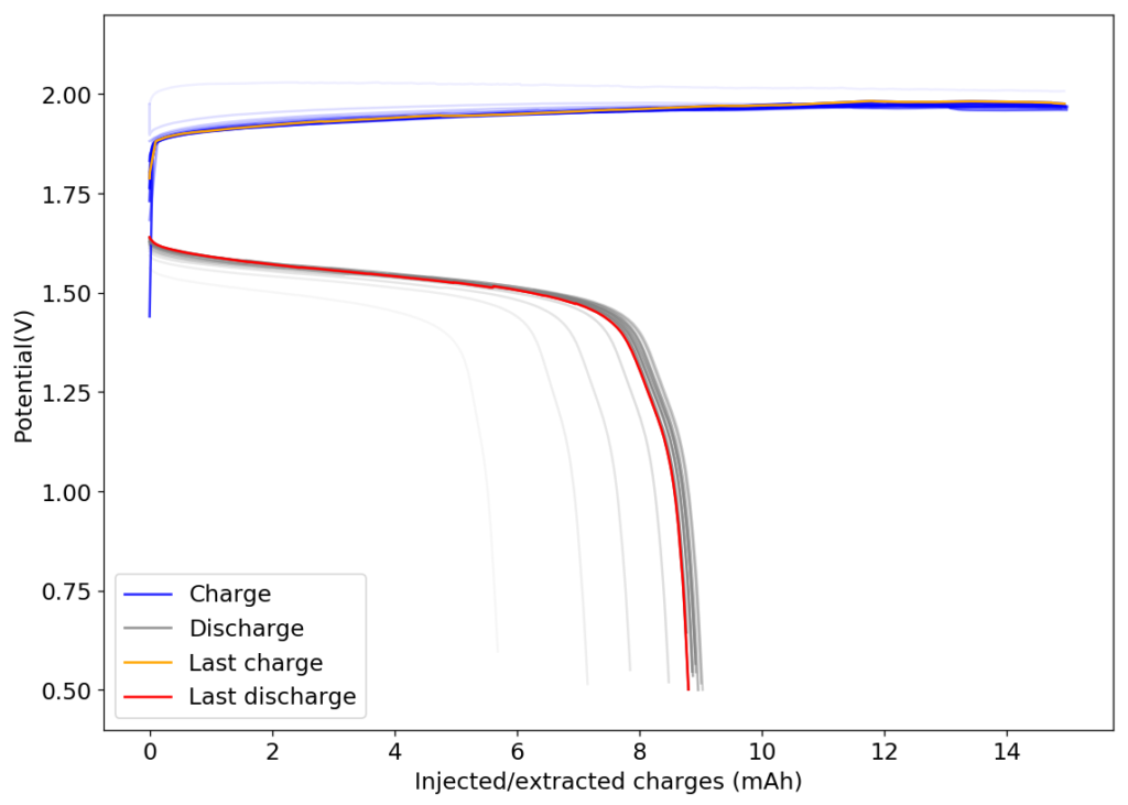
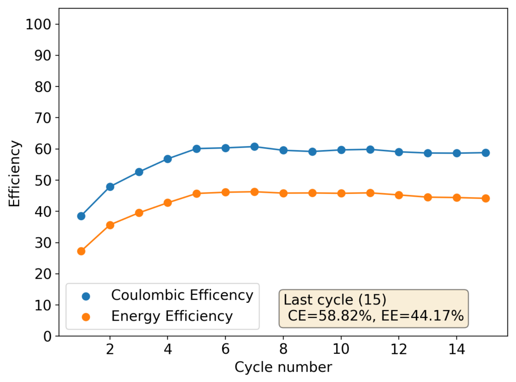
The results, shown below, illustrate the problem of trying to create a Zn-Br battery without a sequestering agent. The lack of a sequestering agent means that the formed bromine is easily able to exit the cathode material and go into the separator, migrating towards the anode. The cell’s behavior is similar to my batteries with sequestering agents, as during the first few cycles the cathode losses a lot of bromine to the media due to the lack of any oxidized bromine species in the separator and therefore starts at a lower Coulombic and Energy efficiency.

Resulting first 15 charge/discharge curves for a Zn-Br battery containing no sequestering agents, charged to 15mAh and discharged to 0.5V, both at a rate of 15mA.

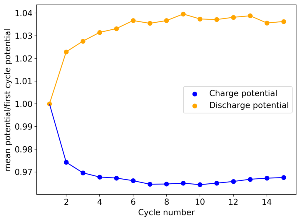
However, as the battery progresses, the Zn-Br battery assembled without a sequestering agent stabilizes at a CE of around 60% and an EE of around 45%, while with a sequestering agent, these values go up all the way to 90% and 65%. It is therefore evident that the sequestering agent does a good job of keeping the formed bromine in the cathode material, while the lack of a sequestering agent makes the battery significantly less efficient.

The energy density also changes quite dramatically, with the sequestering agent battery reaching around 25Wh/L and this design without one reaching only close to 17Wh/L. The use of a sequestering agent improves almost all aspects of the battery, except perhaps the stability of the battery which is lower if the sequestering agent reacts in any way with the electrodes or the bromine as a function of time.

Evolution of charge and discharge potentials for a battery with no sequestering agent.

I am going to continue cycling this battery in order to see if it reaches the same stability limits as my other devices or if it is able to run significantly longer. Batteries containing sequestering agents and charged to 15mAh have shown to deteriorate substantially at around 60-70 cycles, particularly batteries using TMPhABr as the sequestering agent. If these batteries without the sequestering agent are more stable then the stability issues of my designs using a sequestering agent could be assigned to chemical instabilities of this agent within the electrochemical environment.

Zinc Bromine Batteries: Iron impurities in Zinc Bromide solutions derived from Zinc Sulfate

An important issue with Zinc-Bromine batteries is the need for a high purity Zinc Bromide solution in order for the battery to work properly. The use of low-cost ZnBr2 sources, in particular the use of Zinc Sulfate and Sodium Bromide to generate Zinc Bromide solutions, can be problematic due to the presence of large amounts of Iron impurities. In this post I will discuss what happens when you have these impurities in a battery and how you can purify a Zinc Bromide solution to remove iron and achieve better results.

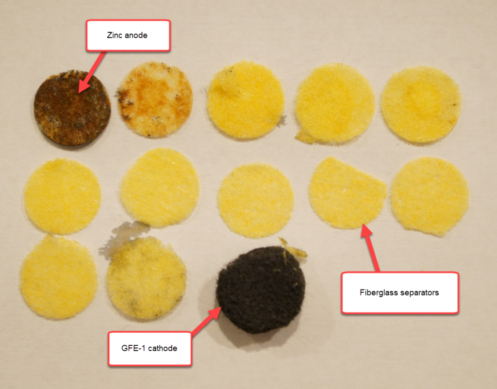
Layers of a Zn-Br battery using a 4.2M ZnBr2 electrolyte derived from the reaction of commercial grade Zinc Sulfate monohydrate and Sodium Bromide. The battery was taken apart after 15 charge/discharge cycles at an energy density of around 20 Wh/L.

The image above shows you the layers of a Zn-Br battery that was taken apart after 15 cycles, charging the cell to 15mAh at 15mA and discharging to 0.5V, the cell has a diameter of half an inch. As you can see, the fiberglass separator layers look very yellow and, although it would be tempting to assign this color to the presence of elemental Bromine, which is true in part, cells constructed with high purity ZnBr2 solutions do not show such a strong yellow coloring. The yellow color is in large part caused by the oxidation of Fe+2 to Fe+3.

Moreover, the Zinc anode is usually a grey or black color in batteries created with high purity ZnBr2 solutions, while in this case, it looks a lot like a rusted piece of Iron. This is no coincidence, as Fe is actually reduced in the anode and then oxidized to insoluble Fe oxide/hydroxide species. The first two layers of the battery show the strong presence of these red Fe+3 oxides, which are non-conductive and significantly hamper the performance of the battery.

Battery performance characteristics for the battery that was dismantled and showed above.

The characteristics of this inverted battery were actually not bad to begin with, achieving max CE and EE values of 81% and 61% respectively. However the discharge curves start showing significant deterioration around the 10th cycle, with strong drops in the discharge voltage around 3-4 mAh into the discharge cycles. This was also shown as a strong decay in the average discharge potential, which during the 15th cycle was around 6% lower than the starting value. This speed of decay is dramatically faster than for Zn-Br batteries created using high purity ZnBr2 solutions.

The above implies that you need to get rid of these Fe impurities if you expect to be able to run a Zn-Br battery that lasts for a long amount of time. Thankfully there is a pretty easy way to do this, which we know from the literature surrounding the purification of Zinc brines (see here). The trick is to use a 3% hydrogen peroxide solution for the preparation of your ZnBr2 solution, instead of distilled water, when you dissolve the Zinc Sulfate and Sodium Bromide salts. This causes all the Fe to be oxidized to Fe+3 and to precipitate out of solution.

A reaction containing 62g of NaBr, 52g of ZnSO4.H2O and around 50mL of a 3% hydrogen peroxide solution. You might want to add around 50-100mL of distilled water before filtering to make your processing easier.

The image above shows you how this reaction looks. The Fe compound generated is very red, while the precipitated sodium sulfate is white, giving you this sort of look. The reaction takes around 6 hours to fully complete – for all the Fe to be precipitated out – time after which you can filter the solution and measure the density of your resulting brine to figure out what approximate concentration you have (per my previous post). It’s crazy how much Iron the “high purity” agricultural grade Zinc Sulfate Monohydrate contains!

It is also worth noting that this ZnBr2 solution will contain a significant amount of peroxide so you either need to heat the solution up to fully decompose the peroxide or wait till all the peroxide is decomposed at room temperature before actually using the solution in a battery. To be absolutely sure, you can also use H2O2 testing scripts (like these), to figure out whether you have any peroxide left before considering a solution to be battery-ready.

With that said, this process is absolutely necessary to build Zn-Br batteries if you’re deriving your Zinc Bromide from an impure source, as a Zn-Br battery containing large amounts of Fe will degrade and stop working pretty fast as a function of time. If you want to test your ZnBr2 solution you can add a couple of drops of H2O2 to a sample of it and see if any Fe precipitate forms.

Zinc Bromine Batteries: Is there anything that can work just like propionitrile?

Trying to improve on Zinc-Bromine batteries, it seems that the use of non-aqueous solvents in order to better sequester the bromine would be ideal since successfully sequestering the bromine in a static battery configuration is hard, even when ammonium salts are used as sequestering agents. This is because the salts are largely insoluble in ZnBr2 solutions, so the sequestering agent needs to be included as a solid, which can only be done in very limited amounts without strongly degrading battery performance. This is what I have tried to do with TMPhABr saturated GFE-1 cathodes, but the amount of Bromine I can sequester before it leaks out into the rest of the cell is quite limited. This is evident when I take apart fully charged cells and the entire cell is tinted with a strong orange color.

Ideally we would want to have a phase that is separate from the aqueous ZnBr2 phase but that has a higher affinity for bromine, is able to dissolve a significant amount of ZnBr2 (>1.5M) and is non-toxic. Propionitrile has been shown to be a decent candidate to achieve this, see here, but it is not an ideal candidate for a DIY solution because it is hard to get in most cases and can be a significant hazard for human health. It is catalogued as a dangerous chemical for transport in the US and EU and its use therefore poses a lot of additional restrictions and problems.

Most polar solvents that can dissolve ZnBr2 to some extent and are electrochemically stable – meaning they won’t get oxidized at the cathode – are sadly also miscible with water. This means that they don’t form a separate phase, which is an absolute requirement. I tried using propylene carbonate mixed with tetrabutylammonium bromide (TBABr) – which does not mix with ZnBr2 solutions – but this was a complete failure due to the fact that the bromine and perbromides formed actually prefer the ZnBr2 phase to this organic phase, even at lower concentrations of TBABr.

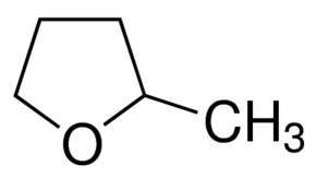
2-Methyltetrahydrofuran BioRenewable, anhydrous, >= 99 %, Inhibitor-free |  96-47-9 | Sigma-Aldrich
Me-THF, a new organic solvent candidate I will be trying in Zn-Br batteries to serve as a cathode side electrolyte and sequestering media.

I then continued my search for the “perfect solvent” for this, reviewing a lot of the literature on non-aqueous solvents in batteries and on “green chemistry” to find the solvent with the perfect polarity, ability to dissolve Zn-Br, affinity for Bromine, immiscibility with water and low toxicity. I think I might have found a solution in the form of 2-methyltetrahydrofuran or Me-THF. This solvent is a highly polar ether, it can dissolve high amounts of ZnBr2, it has a high affinity for elemental Br, it’s significantly less toxic than propionitrile and, alike propionitrile, it does not mix with water or ZnBr2 solutions. It is also electrochemically stable and is also safe enough that it’s available for purchase on ebay/amazon, so I decided to buy some of it to do some basic experiments and see if this solvent finally provides the answer we have been looking for,

Interestingly the density of Me-THF is quite low – around 80-90% that of water – so it will naturally rest on top of it. This means that it is naturally suited for an inverted cell configuration (cathode on top, anode on the bottom), which is what we want (see here). I couldn’t find what the partition coefficient with ZnBr2 solutions in water is, but the hope is that we should be able to get enough ZnBr2 in the ether to have a successful battery starting with a 3M solution of ZnBr2 in water. Batteries with Me-THF likely won’t require the use of any ammonium salts – as in the propionitrile paper mentioned above – since the affinity of the Br for Me-THF is high enough to keep it away from the aqueous phase.

Alike with PC, it is hard to know what to expect, so I would advice waiting for some of my results before going out to buy this solvent. Who knows how it will work in practice!

Zinc Bromine Batteries: Increases in resistance when using TW20+PEG-200 containing solutions

As I showed in my last article on Zn-Br batteries using a Tween20+PEG-200 electrolyte, the batteries had no issues with dendrite production on the zinc anode but faced substantial deterioration of both the charging and discharging voltages as a function of time. I repeated the experiment using a Zinc anode to see if this phenomenon was consistent. The tests below were carried out for a battery that used a GFE-1 cathode pretreated with 10% TMPhABr and an electrolyte containing 1% PEG-200, 1% Tween 20 and 3M ZnBr2. The cell used a 0.2mm Zinc anode and graphite electrodes within the Swagelok cell.

Charge/discharge curves, charged to 15mAh at 15mA, discharged to 0.5V.
CE and EE as a function of the cycle. The cell was run for 8 cycles.

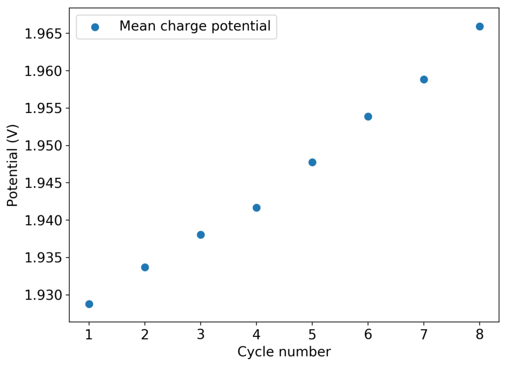
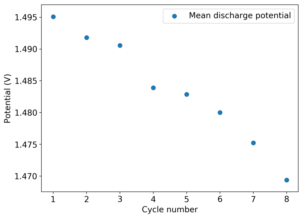
As you can see in the images within this post, although the CE and EE values of the battery remain fairly constant through the test, the mean charge potential increases and the mean discharge potential decreases as a function of the cycle number. This is showing that there is an overall increase in the internal resistance of the cell as a function of time, which appears to be linear and doesn’t seem to become smaller with time. Other cells that were charged to even larger numbers of cycles continued to show this deterioration, up to the point where the EE and CE of the cell started to decay and the cell started to fail.

This behavior points to some irreversible process happening within the device that is fundamentally affecting internal resistance. This has to be either a surface modification of the electrodes or an irreversible loss of conductivity in the solution. The first can happen due to bromide/perbromide interactions in the cathode, zinc oxide deposits in the anode caused by a local increase in pH due to hydrogen evolution or even the appearance of some insoluble polymers in the cathode due to electrochemical reactions of the additives.

Mean charge potential as a function of the cycle number
Mean discharge potential as a function of the cycle number

There is some evidence that cathode structure does deteriorate with time under the cell conditions. There is a significant amount of graphite that can be wiped off the Swagelok cell electrode after opening up the cells – while the graphite electrode was sanded and completely clean upon cell fabrication – which might point to the electrode itself or the GFE-1 cathode material degrading. I am currently running an experiment using a titanium electrode with a GFE-1 cathode to rule this out.

About the stability of the additives and sequestering agent, it might be worth it to carry out some cyclic-voltammetry (CV) experiments to investigate the stability of the organic additives being used to see if any of them can fundamentally degrade under these conditions. The TMPhABr could be especially susceptible, given its aromatic amine character. If the sequestering agent can deteriorate under these conditions, then we might be unable to use it as an effective agent and we might need to resort back to TBABr or TPABr. The Tween 20 might also be electrochemically vulnerable, so this additive also needs to be studied in this manner.