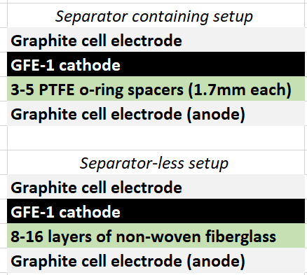
During my journey to understand and built better Zn-Br batteries I have constructed batteries using both separator and separator-less setups. In the separator containing setups there are layers of non-woven fiberglass tissue paper between the anode and cathode while the separator-less setups use PTFE o-rings as spacers to maintain the distance between the cathode and anode constant. Through my experience with both of these setups I have gained some useful experience that I am going to share within this post. More specifically I will be showing you a list of pros/cons for each architecture.
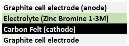
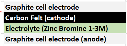
Non-woven fiberglass separator containing setup
Pros:
- Electrolyte is absorbed within the separator, therefore the cell can be moved freely for short periods of time without issues.
- Since the separator is solid it can be compressed more, leading to better battery characteristics.
- Compression is homogenous through the entire cell, which makes devices more reproducible.
- There is no spacer to keep electrode distance so all the effective cross-section can be used which leads to a more efficient use of cell volume.
- Slower diffusion of bromine across the device, which leads to slower self-discharge.
- Easily scalable.
Cons:
- Cell cannot be easily maintained or electrolyte easily replaced.
- Dendrites irreversibly damage the separator since the separator is physically torn by the zinc dendrites.
- There can be significant edge effects at the edge of the separator, as charges flow more efficiently around these areas since their interaction with the separator is weaker.
- Absence of important edge effects in the device as diffusion speed is likely constant through the cross-section.
PTFE o-ring spacer setup
Pros:
- Faster ion diffusion due to the absence of any additional material between most anode and cathode which can lead to better charge characteristics.
- Electrolyte can be replaced easily by opening up the cell and refilling or washing the cell components.
- Zinc dendrites are not irreversibly destructive, causing only self-discharge issues as they reach into the cathode. When the battery is at rest dendrites tend to re-dissolve as bromine diffuses from the cathode to the anode.
Cons:
- Compression of a spacer setup can cause a carbon felt cathode to be compressed into the o-ring, effectively getting closer and closer to the anode and sometimes cutting the cathode material. This effect is difficult to control well, which causes reproducibility problems between devices.
- The devices cannot be moved because sloshing of the solution can cause important issues, such as self-discharge, to accelerate exponentially.
- Due to the spacer taking some volume in the device, the amount of usable coss-section decreases, which causes substantial losses in device energy density.
- Not easily scalable as electrodes will tend to sag when larger cross-sections are used, therefore requiring the design of a scalable spacer design (like a PTFE grid) which is likely to be expensive.
After thinking a lot about the above characteristics, it seems to me that the main important disadvantage of the spacer setup is its vulnerability to become damaged irreversibly by the appearance of zinc dendrites. If these are not a substantial issues, then a fiberglass separator setup would be significantly better approach – both in terms of cost, reproducibility, scalability and performance – relative to a PTFE spacer based setup using no separators.
Let me know what you guys thing about the above!