Category Archives: Uncategorized

Problems with the Fe-EDDHA|Mn-EDTA flow battery system

I wrote a blog post about some of my first tests of the electrochemistry of the Fe-EDDHA|Mn-EDTA system and how I planned to build a flow battery using this chemistry. I have since been able to setup a flow battery and perform some initial experiments. So far, there are several fundamental problems with the above chemistry that strongly affects its viability. I will discuss these problems below.

Fe-EDDHA solubility and pH. The Fe-EDDHA is more soluble at more basic pH values and its solubility at neutral pH is limited to perhaps only 0.1-0.2M. Furthermore, there are several less soluble impurities present – different isomers of the EDDHA – which have to be filtered before the cell is operated. Additionally, the pH changes substantially upon charge/discharge, which causes problems with the Mn-EDTA side (you’ll see later on).
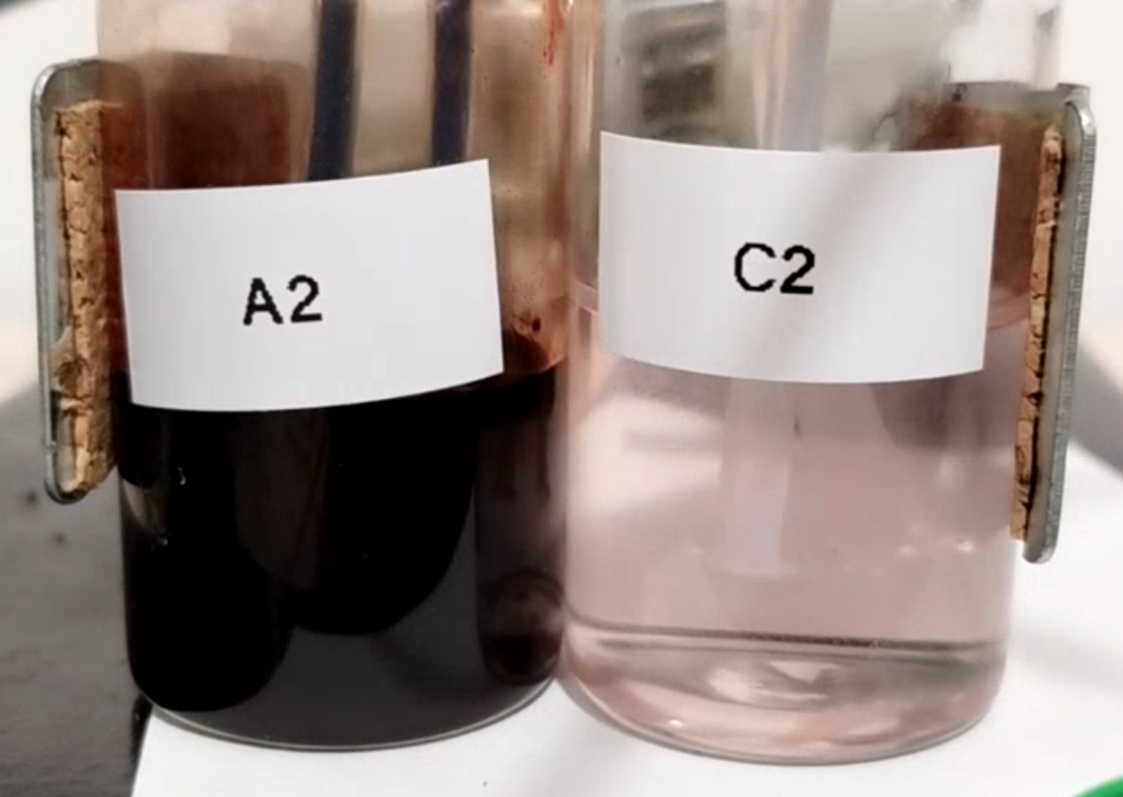
Fe-EDDHA anolyte (A2) next to Mn-EDTA catholyte (C2) solutions, both at around 0.2M.

Difficulty in working with Fe-EDDHA solutions. The solutions of Fe-EDDHA are very deeply red, basically black at the concentrations we’re working with here. This means that it is very hard to tell if there are any insoluble substances in the solution. It is also hard to tell the charge state of the solution, as it will only slowly become more transparent as the Fe-EDDHA is reduced to its Fe(II) form.

Fe(II)-EDDHA sensibility to oxygen. Once the Fe-EDDHA is reduced in the anode, the liquid becomes incredibly sensitive to any oxygen dissolved in the solution, which will quickly oxidize the Fe(II)-EDDHA back to Fe(III)-EDDHA. Given that I currently have no means of purging my system of oxygen, this makes it impossible for me to run flow batteries using Fe-EDDHA right now in a reliable way.
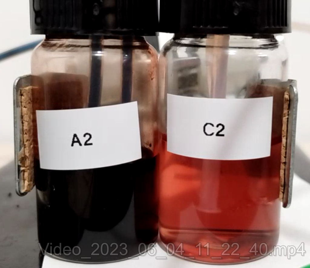
Anolyte and catholyte of the system. You can observe the red color of Mn(III)-EDTA appear in the catholyte (C2) as the flow battery is charged.

Mn-EDTA stability at higher pH. The oxidized form of Mn-EDTA, which is Mn(III)-EDTA, is red at a pH below 6.5 and yellow at a pH above 6.5 (you can see that yellow in a previous post). However, the yellow molecule is extremely unstable, therefore it is very important for pH to remain below 6.5. However, at a pH below 6.5 the solubility of the Fe-EDDHA drops substantially. The differences in pH between charge and discharge means that both systems are virtually incompatible, because as the Fe-EDDHA charges it induces changes of pH that very negatively affect the decomposition of the Mn-EDTA catholyte.

For all the above reasons, I decided I no longer will explore the Fe-EDDHA|Mn-EDTA system, as I currently don’t have the technical setup that is necessary to properly study it. Furthermore, the low solubility, difficulty of working with the Fe-EDDHA solutions and the problems with pH, make this system more complicated than I was hoping for, especially in a system I hoped to be simple for DIY.

I will continue to study flow batteries based on Mn chemistries, including Mn-EDTA (as these are very interesting), but I will likely change the anolyte to something that is more aligned with my current setup. Most likely I will have to compromise and use a potentially higher density, low cost anolyte, that will involve plating a metal on the carbon felt anode, like Zn. Hopefully in this manner I’ll be able to find a low cost setup to bring a DIY solution with a capacity at least in the 10-20Ah/L range.
An improved DIY cation exchange membrane with less degradation using a Daramic PE microporous separator as base

In my previous posts about cation exchange membranes, I created a membrane using cross-linked PVA over a cellulose support. For this purpose, I used a filter paper and then applied successive layers of a solution with PVA, phosphoric acid and citric acid, which I then heated to 150C to create the final cross-linked membrane. This procedure created a membrane that had high permselectivity, decent in-plane conductivity and that could be produced for very low cost.

The problem however, came from the fact that the membrane degraded in the presence of Mn3+ , which was generated when the Mn|Fe chemistry I am testing is cycled. The degradation became apparent as the red color of the Mn3+ faded with time, although no crossing of the Mn3+ across the membrane happened. There were also a lot of bubbles generated on the membrane on the Mn side, which is further evidence supporting this degradation mechanism.

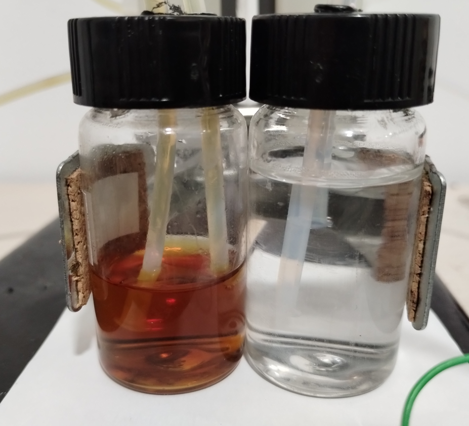
These two solutions have been pumped continuously through a flow battery cell with the crosslinked PVA/daramic separator. After The left solution is 0.25M Fe-EDTA, the right solution has only distilled water. There is no evidence of any cross-over of Fe-EDTA after 24 hours.

I think that this degradation happened mainly because of the cellulose, which is the most reactive part of the structure. To try to alleviate this problem, I decided to move away from the cellulose support and try to cross-link the PVA over a more stable substrate. To achieve this I performed the same cross-linking process, but this time doing it over a daramic polyethylene separator as support.

The Daramic is a microporous polyethylene separator – commonly used in lead acid batteries – which can be purchased for very little cost (only a few dollars per square meter). The daramic has a well defined pore size that can be filled with the PVA solution. Upon heating and reapplication of the solution, the pores can be filled with the cross-linked cation exchange material, with the daramic matrix providing the main source of structural support.

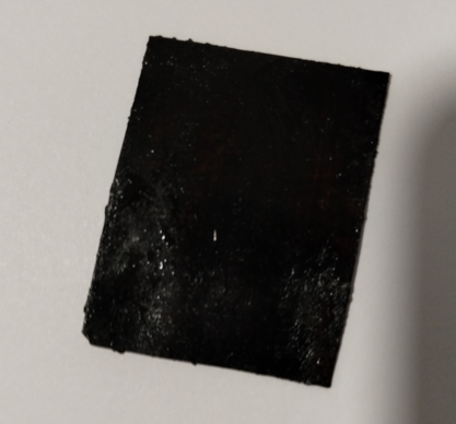
This is how the Daramic membrane looks after the PVA has been applied and crosslinked within its pores.

After the material has been saturated, heated to dryness and resaturated/redried multiple times with the polymer solution (10mL 14% H2SO4, 15g PVA, 8g citric acid, 250mL of water), the Daramic is then heated to 150C for one hour to finalize the process. The Daramic film created is black and has a permselectivity greater than 95%, measured in a cell with 0.1M KCl | 0.5M KCl. The first image in this post also shows how absolutely no cross-over of an Fe-EDTA salt is seen after running by this PVA+Daramic separator for more than 24 hours. When using just the Daramic microporous separator, cross-over is seen within minutes.

The great news is that the Daramic support is made of polyethylene, so it is very unreactive. The crosslinked PVA is also way less reactive than the cellulose, enough so that it now doesn’t react with Mn3+. I generated some of this material through electrolysis of an Mn-EDTA solution, and the crosslinked daramic didn’t bubble or degrade the Mn3+ after a couple of hours.

Sadly my potentiostat broke due to a small lab accident (spilled liquid over it), so I am waiting for a new potentiostat to be delivered to perform the first cycling experiments using this new cation exchange separator.

Nafion equivalent permselectivity values using a DIY PVA/Cellulose cation exchange membrane

During the past couple of weeks I have been working on cation exchange membranes using PVA/cellulose (see here, here, here). The idea is to create a membrane that can replace Nafion in a pH neutral flow battery built using an Fe anolyte and a Mn based catholyte. In this post I will share the first results that are up to par with those of a Nafion membrane.

My initial idea was to both crosslink and add anionic sites to the PVA by using phosphoric acid with urea as a catalyst, heating the membrane to >150C in order to perform the esterification process. This worked to a decent degree, achieving membranes with permselectivity values above 80% with sheet resistance values around 10x those of Nafion membranes.

Membranes annealed at 150C (left) and 100C (right)

However there were some obvious issues with this process. The first is that the membranes produced had some stability issues, their permselectivity would drop with time – due to lack of enough crosslinking – and the mechanical stability of the membranes also left a lot to be desired. Both of these issues were likely due to limited crosslinking of the membranes, as forming a double phosphoric acid ester is not a very favorable process, even in the presence of urea.

I would see Fe-EDDHA-1 leak across the membrane within around 24 hours of setting up my cells, with the transparent side turning a slight pink within that timeframe. The permselectivity would also drop from 80% to around 40% within that timeframe. It was obvious that these membranes had components that were still dissolving or at least creating cavities that allowed too much water to flow through.

Thinking about this, I searched for possible crosslinking agents to enhance the issue. I also wanted to avoid usage of anything toxic, like glutaraldehyde, as the space where I carry out these experiments has limited ventilation, plus I want to avoid exposing myself or my cats to harmful substances. Expensive substances were also out of the question, like sulfosuccinic acid.

Multiple results of membranes being prepared using this method (each one is around the diameter of a 25c US coin)

Reviewing papers on the subject, citric acid appeared to be a viable substance. It is a tricarboxylic acid, so it would be able to crosslink cellulose with PVA, PVA or cellulose with themselves and also keep some exposed anionic carboxylic groups to provide cation exchange capacity. Adding phosphoric acid would also catalyze the esterification reaction plus also provide some phosphorylated sites for enhanced permselectivity.

The process for preparing these membranes is as follows:

  1. Prepare a solution by adding 15g of PVA to 200mL of water (solution A).
  2. Place solution A in a fridge for 48 hours, with occasional stirring/shaking. Surprisingly, cold conditions are much better for dissolving PVA because they discourage agglomeration.
  3. Wait till solution A is fully homogeneous, keep longer in fridge and shake/stir as needed.
  4. Prepare another solution by using 0.5mL of phosphoric acid (81%), 0.5g of citric acid and 15mL of solution A. This solution is stirred until everything is completely homogeneous (solution B).
  5. Dip a filter paper in Solution B. I used Stony Lab 101 but other fine grain filter papers should work just as well. Make sure all excess has dripped off and tap with paper towels to remove any excess.
  6. Place on a hot plate at 80C for 3min
  7. Flip it to the other side for another 3 minute.
  8. Use a brush to paint solution B on the filter paper while on the hot place.
  9. Wait for 3 minutes.
  10. Flip the filter paper and paint the other side, wait another 3 minutes.
  11. Repeat steps 8-10 three times.
  12. Increase the temperature to 150C.
  13. Flip the membrane every 10 minutes for one hour or until the membranes appear fully black. Put a petri dish on top if needed to keep the membrane flat.
  14. Allow the membrane to cool to room temperature.
  15. Place the membrane in a solution with 10g/L of potassium or sodium carbonate to neutralize any remaining acid, they can be stored in a 0.5M NaCl solution.

The membranes that result from this process are black in nature. However they do not feel like charcoal and do not crumb easily. Instead, they have the feeling of a piece of plastic film, which is exactly what we are looking for. Several papers discussing citric acid crosslinking of different polymers do have resulting black films, so this isn’t necessarily a bad thing.

I was also very pleasantly surprised by the permselectivity measurement for these membranes. Measuring the potential across NaCl 0.1M | NaCl 0.5M using identical Ag/AgCl reference electrodes, the potential is 38-39mV, meaning that these membranes have permselectivity values >99%, which is equivalent to that of the best Nafion membranes. Adding 0.01g of NaFeEDDHA to the NaCl 0.5M side – which makes it dark red – I could see absolutely no crossover of FeEDDHA-1 to the other side of the half-cell experiment within 48 hours of testing. There were also no drops in the permselectivity which remains extremely high. The sheet resistance measurements are also very favorable, with in place sheet conductivity values now in the <50 ohm/cm2 range.

Overall, I am pleased with this DIY membrane result. The crosslinking of PVA using citric acid and phosphoric acid on a cellulose matrix provides you with a very robust membrane that has some wonderful characteristics. This will be my base membrane for the construction of Fe-Mn flow batteries. This membrane is also very low cost.

Measuring and improving the performance of PVA/Cellulose cation exchange membranes

In a previous post I described how to create a DIY cation exchange membrane using some easy to get materials. These membranes could achieve significant permselectivity values, but still far away from those required to create membranes for a robust flow battery. Additionally, the sheet resistance of these membranes – which I measured using a 4 contact electrode method – was quite bad, with values often greater than 6000 ohm/cm2. The through plane resistance was around 3x that, although my method for through-plane resistance measurement is not reliable yet.

Some of the last membranes I produced using a PVA solution with a pH in the 6-7 range. The membrane remains an off-white yellowish color, but does not oxidize as in my previous tests.

In this post, I want to talk about the advancements I have made to improve the fabrication of these membranes. First of all, I have lowered the preparation temperature to 150C, this avoids charring the membranes and improves reproducibility. I also added 80 minutes of additional time at these temperature once all the PVA coats have been put on, this improves crosslinking and drastically reduces the solubility of the membrane in water (to the point where it becomes fully insoluble).

I have also found out that decreasing the acidity by adding some potassium hydroxide also helps retain membranes structure, increase permselectivty and decrease sheet resistance. This matches some papers on cellulose phosphorylation using potassium phosphate and ammonium phosphate salts, with solutions that have much higher pH values than phosphoric acid. The higher pH helps preserve the structure of the cellulose and PVA, as a lack of acid reduces the changes of degradation of the cellulose and PVA. The phosphorylation still happens, thanks to the urea catalyst present.

With this in mind, the membranes can probably be made using monopotassium or monoammonium phosphates, much more readily and less dangerous chemicals compared to concentrated phosphoric acid and potassium hydroxide.

One of my last experiments to measure permselectivity. The cell to the right contains a very small amount of NaFe(EDDHA), which has a very deep red color. This makes it very easy to see membrane crossover.

The best values I have achieved so far are a permselectivity of 80% and a sheet resistance of 373 ohm/cm2. These are still much worse than those of commercially available membranes, but certainly better than the values I was achieving before.

From the parameters I have tested, the cross-linking temperature and pH seem to be the most important to the qualities of the membrane, so I will try to study these too with a bit more detail to find out if I can produce membranes with better qualities. Increasing the concentration of P at higher pH values with higher urea quantities might also help achieve better cross-linking.

A DIY cation exchange membrane with PVA and cellulose

In previous posts (here and here), I have talked about my goal to create an Fe/Mn flow battery and how to do this I will need to create a cation exchange membrane to use instead of Nafion. In this post I will talk about what I have achieved so far, which is the first iteration of a PVA based cation exchange membrane.

Early on, it became clear that polyvinyl alcohol (PVA) was going to be the easiest polymer choice, as it is readily available and easily to functionalize. Phosphorylation also seemed as the easiest route towards functionalization, as highly concentrated phosphoric acid is easy to get and urea catalyzed phosphorylation reactions of PVA are already well known. The introduction of phosphoric acid esters provides the ability of the membrane to repel anions and allow only cation transport.

Experimental setup to measure the potential across one of the membranes created. The potential between the Ag/AgCl reference electrode and graphite electrode is measured with both electrodes on the same side, then the potential is measure again by placing the reference electrode on the opposite side. The membrane potential is calculated from the difference between same side and opposite side potentials. (a small amount of dye was added to the right side so that you can see how the membrane separates the solutions).

My first problem creating a membrane of this sort had to do with casting PVA films and being able to peel them off. These membranes are extremely sensitive and can easily stick to glass or to themselves, making the fabrication process difficult. I tried casting on glass petri dishes – with mold release – and was unable to remove them without breaking them. A friend suggested casting on Al foil instead, so I will be keeping this for a future experiment.

Furthermore, the few times I was able to successfully peel off films, the films then dissolved quite easily in water. Although I thought the phosphorylation of the PVA would provide some crosslinking, it definitely increases the solubility of the polymer in water, making things actually worse. Using things like aldehydes for crosslinking is not going to be work, but perhaps future experiments with boric acid or citric acid would help with this issue.

A breakthrough came when I realized that cellulose is also known to be phosphorylated with phosphoric acid plus urea and that it could therefore be cross-linked through a phosphoric acid ester with PVA. The cellulose could also provide a support, which would greatly enhance my ability to work with the PVA solids.

Final result of the process mentioned below

My fabrication process was as follows:

  1. To 15mL of ice cold distilled water add 1g of PVA, 1g of Urea and 1mL of 81-85% phosphoric acid. This is solution A.
  2. Place in a fridge for 48 hours, with occasional stirring/shaking. Surprisingly, cold conditions are much better for dissolving PVA because they discourage agglomeration.
  3. Wait till solution A is fully homogeneous, keep longer in fridge and shake/stir as needed.
  4. Dip a filter paper in Solution A. I used Stony Lab 101 but other fine grain filter papers should work just as well. Make sure all excess has dripped off and tap with paper towels to remove any excess.
  5. Place on a hot plate at 180C for 3min
  6. Flip it to the other side for another 3 minute.
  7. Repeat steps 4-6 once.
  8. Place on the hot plate with a petri dish on top (to keep it flat) for 1 hour.
  9. The result should be as shown in the image above.

The process seems to work. The resulting membrane is not soluble in water, is sturdy and easy to manipulate and loses the micro porosity of the filter paper. It is quite brown, which means some oxidation has happened, but reducing the temperature or time leads to membranes that are not properly crosslinked, and dissolve quite easily (leaving just a porous cellulose membrane behind).

To determine whether the above membrane is in fact a cation exchange membrane, I can measure its permselectivity. To do this, I measure the membrane potential between a 0.1M NaCl and a 0.5M NaCl solution (more details about this process on the first image in this post). The membranes produced in this way have permselectivity values between 0.5-0.7, which means that the membrane does in fact act as a cation exchange membrane. However, the membrane is nowhere as good as Nafion, which has a permselectivity >0.95 under these conditions.

I will now try changes in the composition of solution A and optimize the curing temperature to increase the permselectivity of the membrane. So far I think the fabrication process is quite straightforward which allows me to reproducibly fabricate the membranes described in this post.