Building a rechargeable battery is not an easy task. Although many great technologies are available (like LiFePO4 or even lead acid batteries), building these batteries isn’t trivial because of the technological hurdles, manufacturing requirements, chemical substances, knowledge and safety requirements. It would be ideal if we had access to an open source rechargeable battery technology that was easy to construct in practice with readily available materials, robust and at low cost.
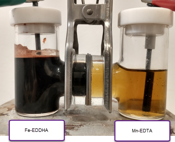
In a previous post I talked about Cu/Mn batteries and how several different papers describe batteries using Cu sulfate and Mn sulfate along with sulfuric acid to create robust batteries with significant capacities, even above 40Ah/L. Such batteries would be close to ideal as they are easy to build, use earth abundant materials and – in theory – are very robust. However, my efforts to reproduce these batteries were plagued with failure as I was unable to reproduce both their reversibility and their capacities.
Furthermore, this Cu/Mn technology using sulfuric acid has been patented by a French company (years before the Chinese articles started sharing the chemistry in 2017). This means that this chemistry is not open source and significant battles could arise from the use of this technology at a wide scale. This also explains why the patent applications mentioned by some of the Chinese researchers in their papers cannot be found (probably the patents were denied because of the preceding French patent).
To tackle my problems reproducing this chemistry, the hurdles with intellectual property and some issues dealing with the solubility limit of copper/manganese sulfate mixes, I have modified this technology to use methansulfonic acid (CH3SO3H) instead of sulfuric acid. Methanesulfonic acid is easier to get than sulfuric acid – because it has no regulatory restrictions – and the solubility of both copper and manganese mesylates is higher than that of their sulfates, meaning that even higher capacities than with sulfuric acid should be possible.
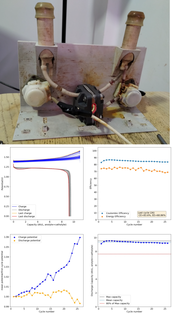
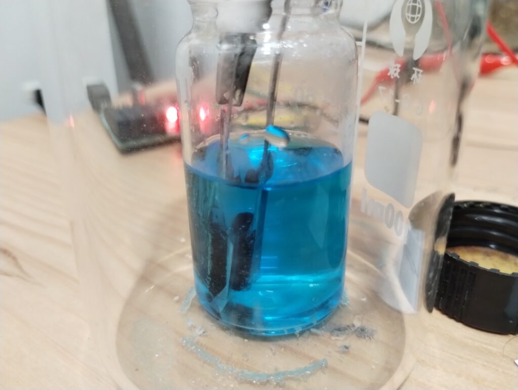
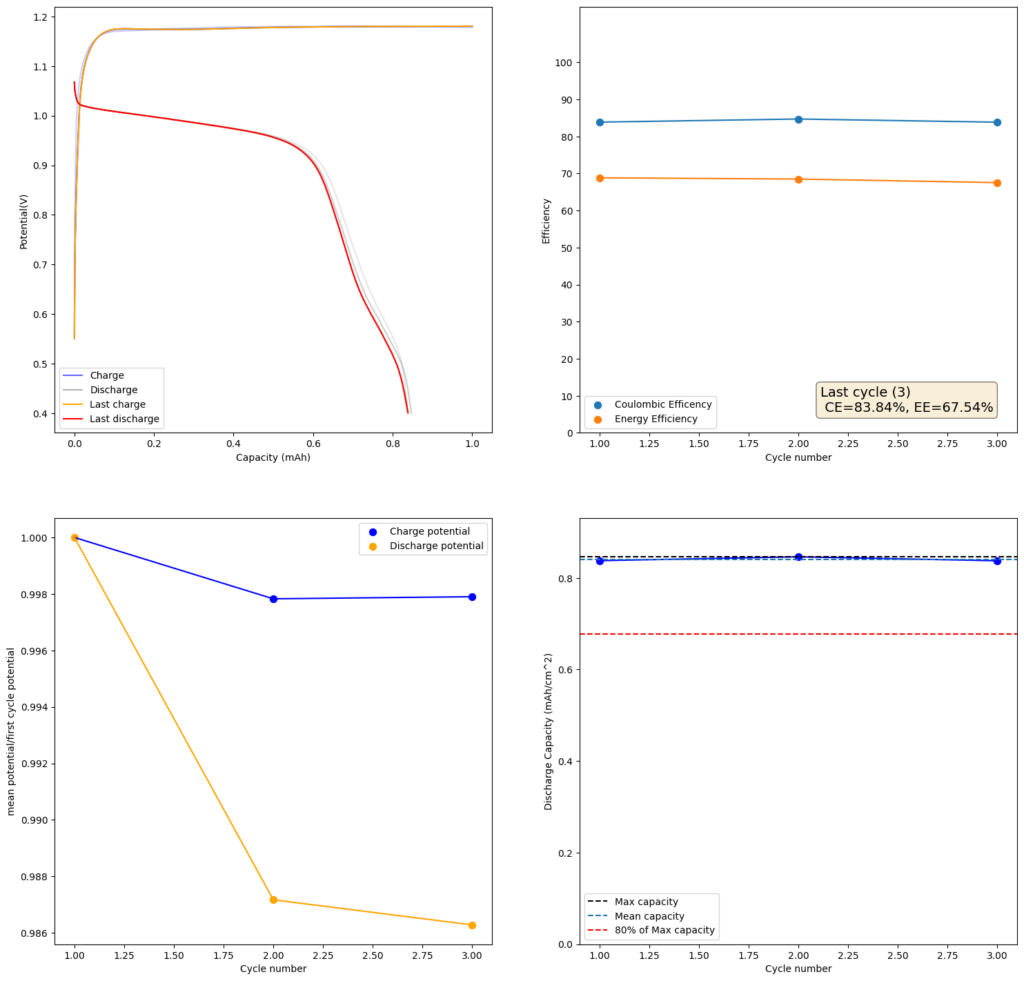
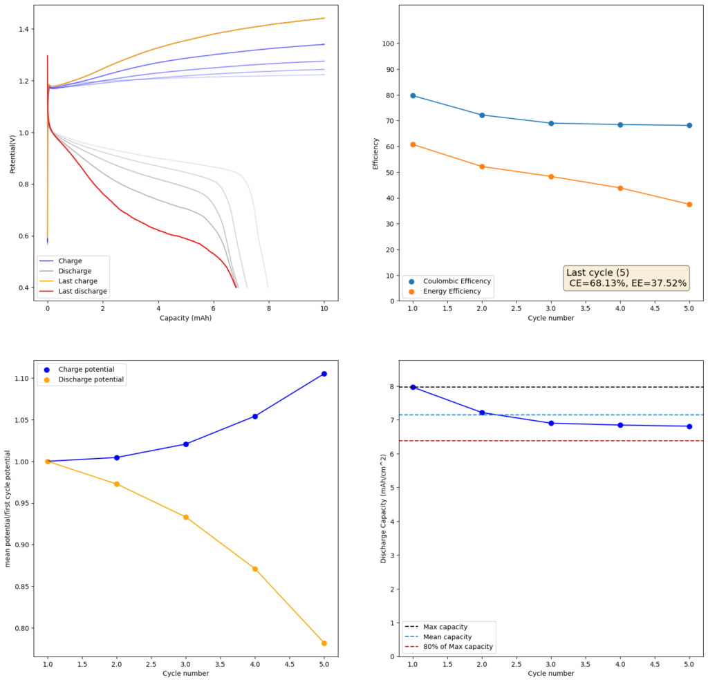
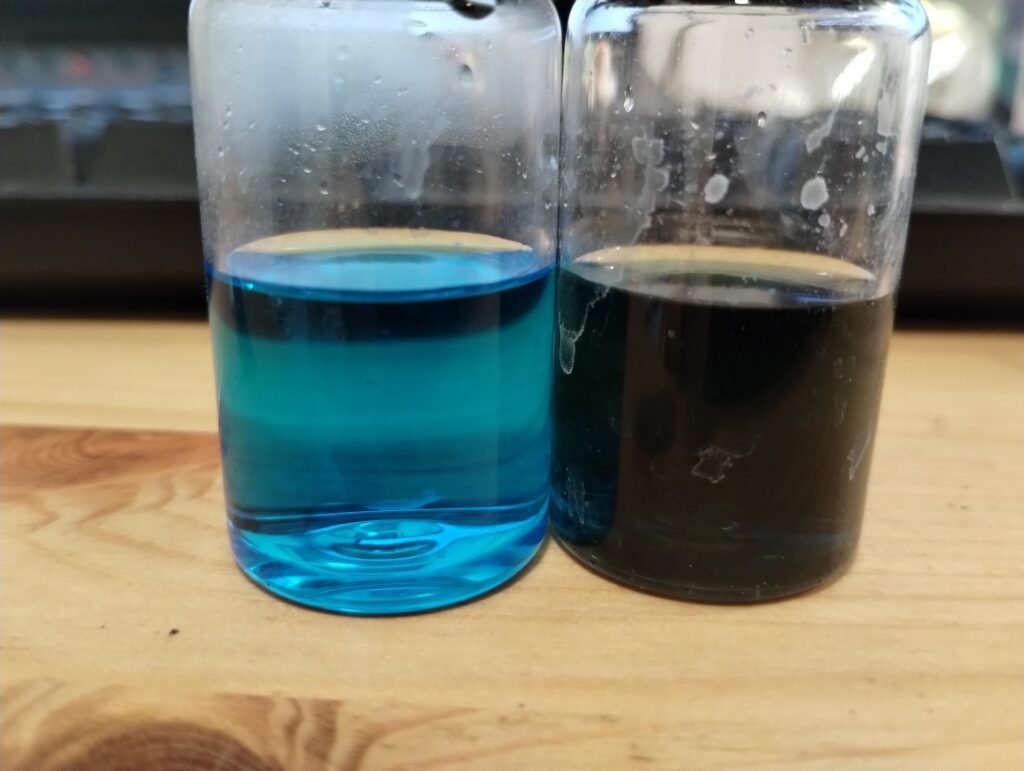
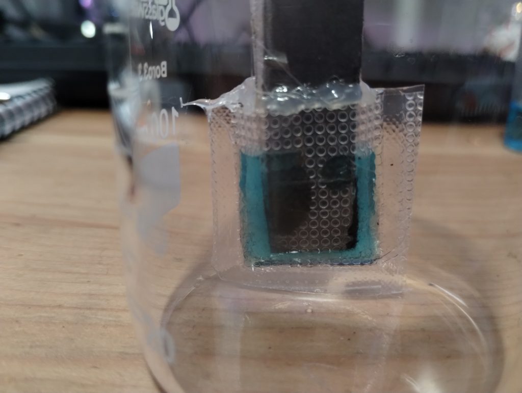
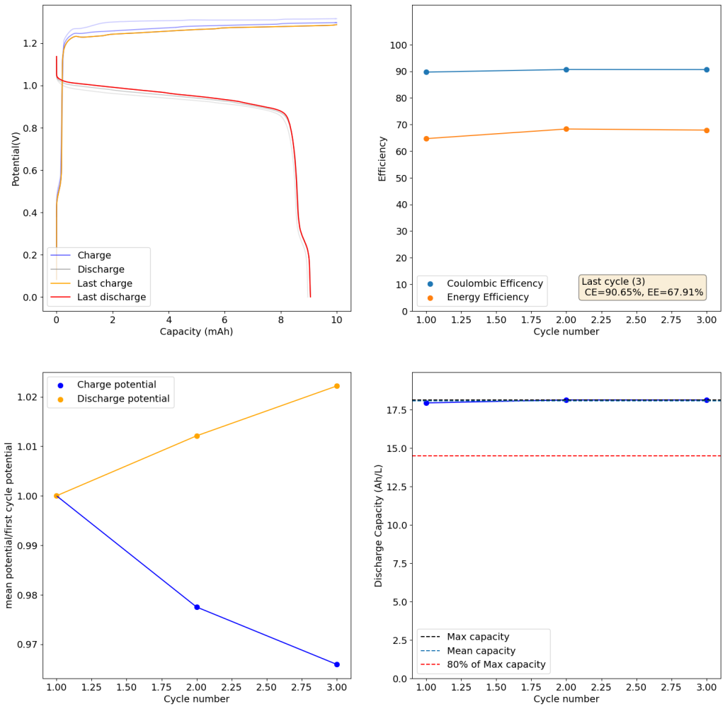
The above experimental results show cycling of the cell shown in the first picture. This chemistry achieves a CE above 90% with an EE above 65%, the cycling is also very stable with very reversible MnO2 formation in the highly acidic media. The electrolyte tested is roughly 0.8m Cu, 0.8m Mn and 1m CH3SO3H. I haven’t tried changing the acid concentration or preparing more highly concentrated electrolytes yet, as I am still fine tuning the cell fabrication process to enhance reproducibility. The cells right now can be charged to 20Ah/L, which is already an interesting level of capacity, although 40Ah/L should be possible.
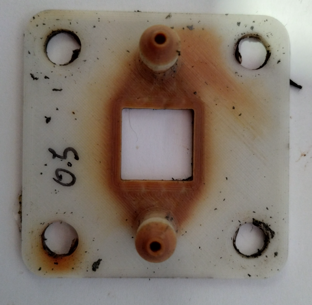
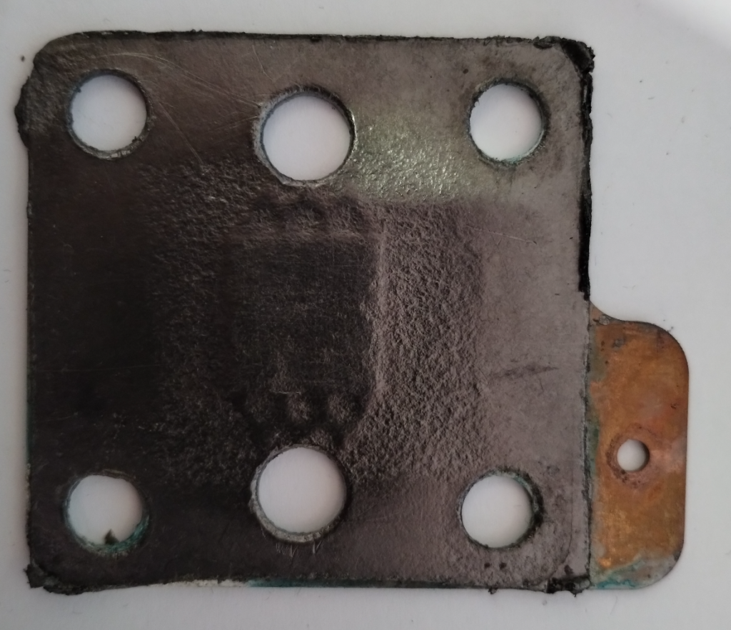
A very important issue I’ve noticed is that dendrites tend to appear around the edges of my Cu anodes due to electric field instabilities, as the Cu prefers to grow in the free solution rather than through the polypropylene separator. This can cause the battery to short when charging to very high capacities). Cells without separators – with just the electrodes hanging parallel as in the case of some of the Chinese papers – could help alleviate the issue. I am also trying passivating the edges using nail polish, to see if this fully solves the issue.
While the Cu/Mn battery chemistry using H2SO4 is clearly patented, the innovation using CH3SO3H is not protected, neither covered by the scope of the current patent nor previously published anywhere else (my innovation to the best of my knowledge). The publication of this blog post should ensure that this technology will remain patent-free.
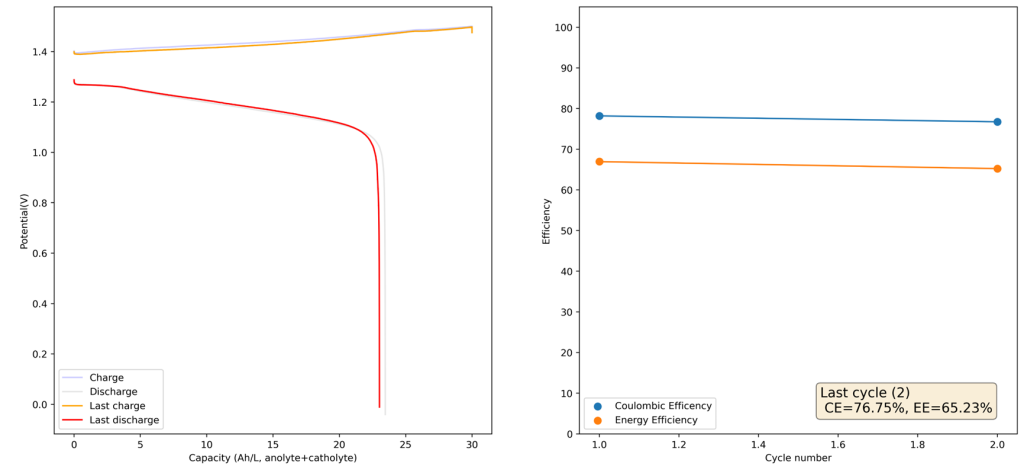
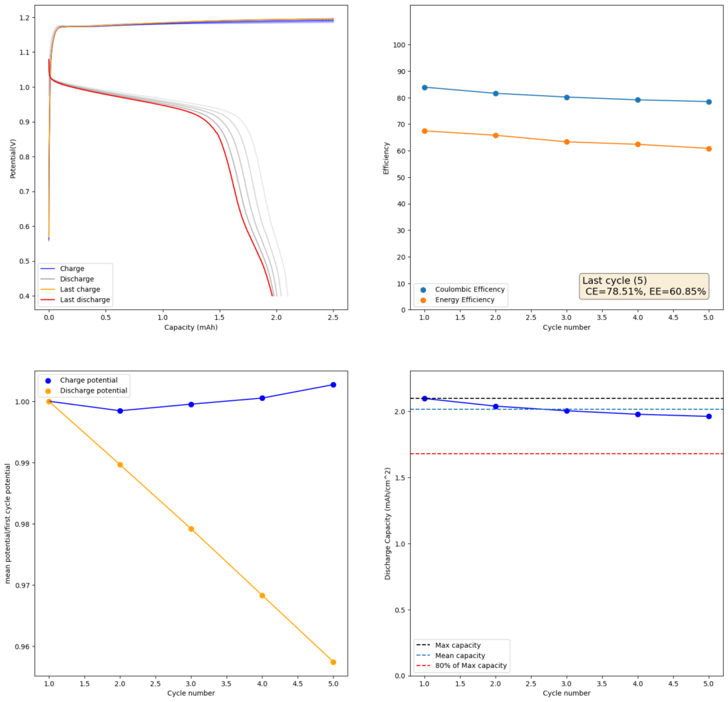
Update:
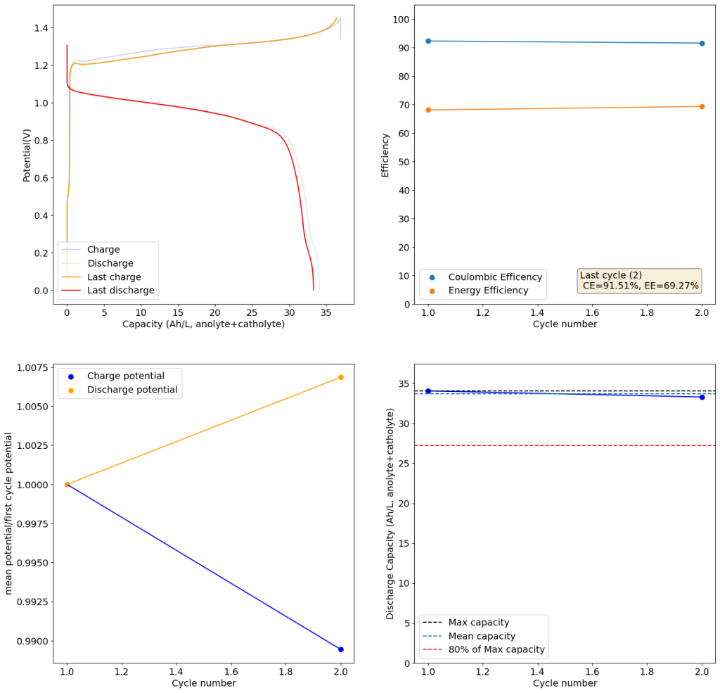
The results above show the cell being charged to 1.45V (This is likely the Nernst limit of the cell). I got a discharge capacity of 33.6Ah/L at 10mA/cm2. Electrolyte is identical to the one mentioned before. The CE and EE are still the same at higher capacity. Dendrites do not seem to get worse provided enough space is left between the edge of the copper electrode and the edge of the separator.