Author Archives: danielfp

The Cu/Mn battery mystery

Since 2019, several groups with Chinese authors have published papers describing batteries using a Cu/Mn chemistry (1, 2, 3). This chemistry is very interesting as it has very cheap chemicals (just copper sulfate, manganese sulfate and sulfuric acid) and doesn’t seem to require any significant electrode preparation. The papers use either carbon cloths, carbon felts or copper plates, all with similar results. However, this chemistry is not as simple or as easy to reproduce as they make it seem. This blog post covers my attempts at reproducing these results.

Testing setup

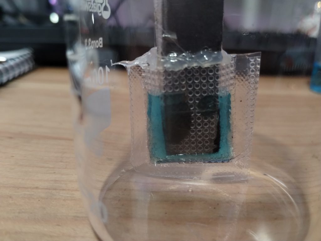
To reproduce these findings I used 3mm thick carbon felt, celgard 2500 as a separator (as tested in reference (2)) and graphoil as current collector material. I also chose an area of 1cm2 in order to minimize material use and simplify calculations. I also treated the felt with a blow torch to improve its wetting abilities, by holding it in front of the torch for 10 seconds per side. I bought copper sulfate heptahydrate, manganese sulfate monohydrate and 15% sulfuric acid from laboratoriumdiscounter.nl. For the electrolyte I prepared a solution containing Cu 0.8M, Mn 0.8M and 0.8M H2SO4. The cell was immersed in 10mL of electrolyte. Given that this is a static battery that deposits MnO2 on the cathode and Cu on the anode, capacity should be limited by electrode volume and not by the volume of solution.

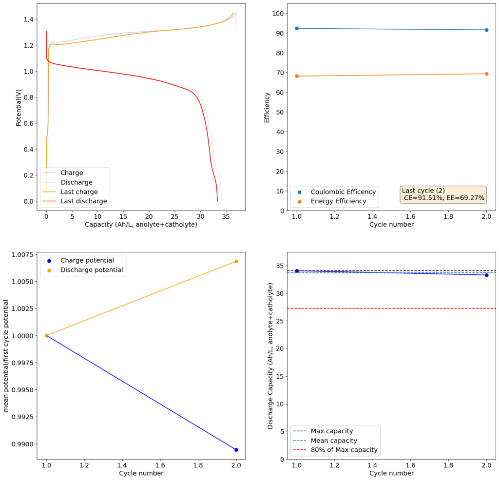
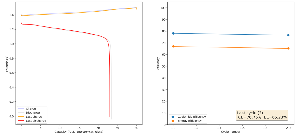
Charge/discharge cycles. Charge was done at 10mA/cm2 to 1mAh, discharge was done to a voltage of 0.4V. Total volume of the electrodes is 0.6mL. Highest discharge density is therefore around 1.2Ah/L.

At low capacities, the battery behaves as shown in the figure above. The CE of the battery is significantly below 100% (~84%) and the energy efficiency is also quite low (~68%). This contrasts with the published literature which often shows CE efficiencies above 90% and energy efficiencies above 70%. I significantly increased the charge to 2.5mAh (4.16Ah/L), which showed a significant decrease in CE, EE and capacity with cycling. Specifically the discharge voltage started decreasing substantially with cycling.

Charge/discharge cycles. Charge was done at 10mA/cm2 to 2.5mAh, discharge was done to a voltage of 0.4V. Total volume of the electrodes is 0.6mL. Highest discharge density is therefore around 3.3Ah/L.

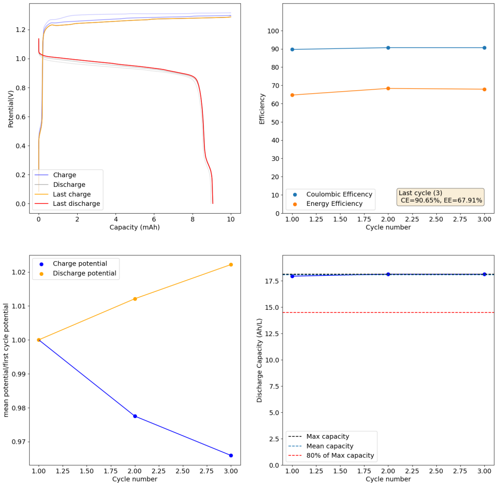
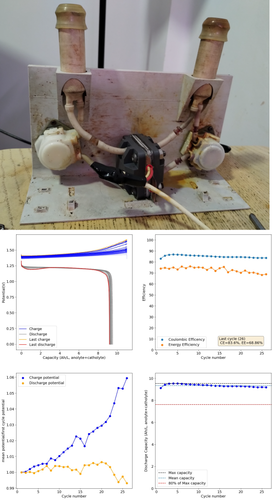
Trying to go to even higher capacities (10mAh), as exemplified in paper (1) which shows values of up to 50mAh/cm2, I got the results showed below. There are very fast decreases in both CE and the EE, with the starting CE being slightly above 85% but dropping aggressively from that point going forward. In contrast with the lower discharge rate experiments, in this case the charging voltage did deteriorate aggressively as well.


Charge/discharge cycles. Charge was done at 10mA/cm2 to 10mAh, discharge was done to a voltage of 0.4V. Total volume of the electrodes is 0.6mL. Highest discharge charge density is therefore around 13 Ah/L.

The electrolyte also shows significant signs of decomposition. The image below shows you a comparison of a pristine vs a cycled electrolyte. You can see how the cycled electrolyte becomes extremely dark, due to the presence of MnO2. This is confirmed by addition of ferrous sulfate, which immediately makes the liquid clear up (as Fe2+ is able to reduce MnO2 to Mn2+). The MnO2 is formed away from the electrode because of the formation of Mn3+ which migrates away and then disproportionates into Mn2+ and MnO2. This explains why there are significant loses in the CE as a function of charging, both due to Mn3+ disproportionation and self-discharge caused by Mn3+ migration into the anode.

Comparison of pristine (left) and cycled (right) electrolyte.

The publishes papers make it seem as though this chemistry is extremely straightforward and reversible, but the facts of Mn3+ formation and disproportionation heavily complicate this approach. It is therefore puzzling to me how the results of these researchers were produced, especially the ones in (1) as their setup uses flooded cells us well, even in the complete absence of any separator. I made similar attempts using copper plates as anodes, 0.4M, 0.5M and 0.6M sulfuric acid and 0.5M, 0.8M and 1.2M Manganese sulfate solutions but couldn’t find any differences in the basic results, the only difference being that current densities needed to be much lower when a copper plate was used, likely due to the much lower surface area.

Let me know if you have any ideas about what I might be missing in the construction and testing of this Mn/Cu chemistry.

Revisiting the idea of using chelates for the Fe/Mn flow battery

On my last post I wrote about the potential of using Fe/Mn in acidic solution to create an Fe/Mn flow battery. I cited a paper published a few years ago which shows that you can achieve reversible Mn3+ chemistry in a solution of sulfuric acid and hydrochloric acid, I then proceeded to confirm this reversibility using cyclic voltammetry of Mn2+ solutions in hydrochloric acid.

However, it quickly became clear from analysis of the paper that this was only at very low capacities. This is because Mn3+ becomes unstable as its concentration increases in solutions, turning into MnO2 and Mn2+.

A 0.5M Fe-DTPA + 0.5M Mn-EDTA solution in an acetate buffer (prepared with 100mL of 8% acetic acid + 10g of potassium acetate)

Given the very low volumetric densities that can be achieved with the acid setup, there’s no option but to revisit the use of more stable and reversible forms of manganese. The best candidate seems to be Mn-EDTA. This complex has already been shown to work in flow batteries at the 0.5M-1.0M range (see here).

I had already thought about using this complex and wrote several posts about its potential use in combination with Fe-EDTA or Fe-EDDHA (see here). However, there is a big problem with the pH compatibility of the Mn-EDTA with the Fe-EDTA or Fe-EDDHA. The issue being that Mn3+-EDTA is only stable under acidic pH conditions, where the solubility of both Fe-EDTA and Fe-EDDHA is limited to around 0.1M. These chelates are only highly soluble under basic pH conditions, which are fully incompatible with Mn-EDTA.

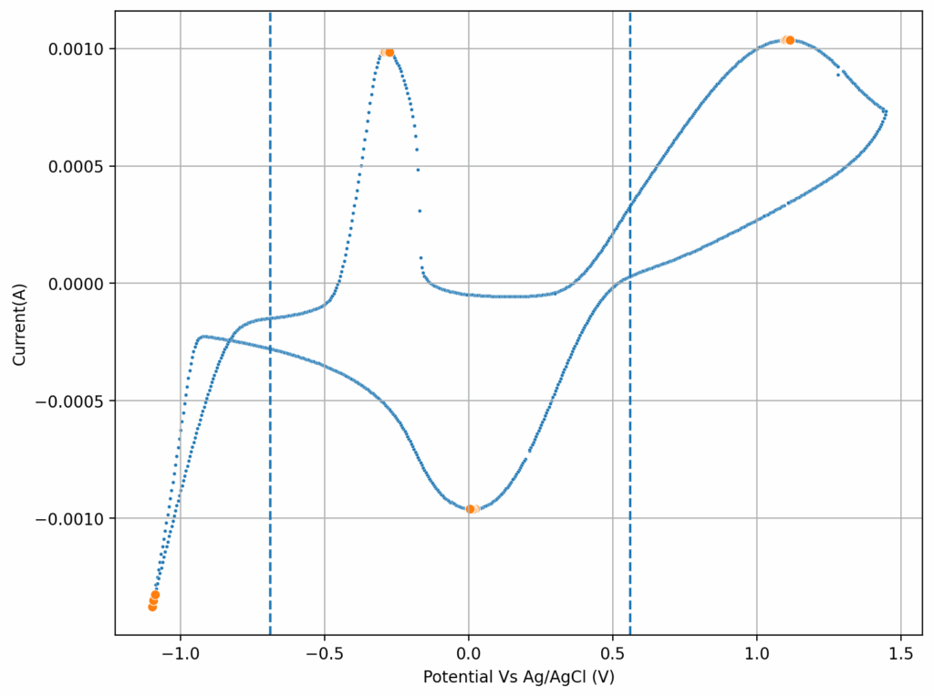
CV of the solution shown in the first image. The half-wave potentials for both reactions are -0.11V and 0.61V, both Vs Ag/AgCl. The above CV was done with a scan rate of 10mV/s.

The question is whether there is any easily accessible Fe chelate that is both compatible with Mn-EDTA in solution (so that we can create a symmetric electrolyte) and that can create soluble solutions at >0.5M concentrations in a pH ~5-6 buffer. Note that I need both chelates to be dissolved at >0.5M at the same time since I want the electrolyte to be symmetric so that it can work using a microporous membrane.

The answer is Fe-DTPA. This chelate is highly soluble at acidic pH values and – best of all – it is soluble enough to actually be in >0.5M solution in the presence of Mn-EDTA at this high concentration. Above you can see a picture of the Fe-DTPA+Mn-EDTA solution. The solution also contains an acetate buffer, which should ensure pH stability on charge/discharge, which should prevent degradation of the Mn-EDTA.

The second image shows a CV of the Fe-EDTA/Mn-EDTA buffered solution, showing that both the Fe and Mn electrochemical reactions are reversible. The half wave potentials are -0.11V and 0.61V, giving us an expected potential for the flow battery of +720mV. This is close to what I had measured before for Fe-EDTA/Mn-EDTA. This proves that the DTPA does not change the electrochemical characteristics of the system very much. The above test also confirms there acetate buffer is stable to the generated Mn3+-EDTA.

The next step is to build a flow battery using the above solution and see what performance characteristics we can get. With the current solutions this system will be limited to around 8-9Wh/L. However I haven’t tested the solubility limits of the chelates in this buffer.

Is Fe/Mn chemistry viable for a true flow battery?

My original idea was to create a flow battery without Vanadium that would contain no metal deposition reactions on either the anodic or cathodic sites. This would be a true flow battery, in the sense that energy capacity would be completely decoupled from power capacity. It would also be compatible with a symmetric electrolyte which would allow the use of microporous membranes. There is currently no low cost flow battery – to the best of my knowledge – that fulfills these criteria, outside of Fe/Mn (with Fe/Cr and V being the only options).

My original idea was to use easily sourced FeEDTA and MnEDTA for this purpose. However it became clear that there are important solubility issues with FeEDTA and MnEDTA plus significant stability issues related with the Mn3+ EDTA chelate, which prevented this battery from actually working. While both FeEDTA and MnEDTA had been used in different flow batteries, no one had put them together on any published research — now I know why.

Cyclic voltammetry of FeCl3 1.5M + MnCl2 1.5M + 3M HCl (concentrations are approximate). Reference electrode was Ag/AgCl, glassy carbon working electrode, graphite counter electrode. Scan rate was 10mV/s.

However, there was a paper published in 2022 that was able to use a symmetric Fe/Mn chemistry by employing Fe chloride and Mn sulfate in an acidic media with a special proportion of sulfuric acid and hydrochloric acid. I wanted to try this out to see if I could actually get an Fe/Mn chemistry that worked. The paper goes into the importance of the hydrochloric acid to generate stable Mn3+ species, but doesn’t say anything about the importance of the sulfuric acid, so I decided to try a hydrochloric acid only approach for starters and see if the CVs showed reversible Mn chemistry.

The first CV I carried out is shown above. This solution was prepared by using 5mL of 15% HCl, 5 mL of 40% FeCl3 and 3g of MnCl2. You can see the reversible reaction for the Fe with a standard potential near 0.45V, you can also see an Mn oxidation peak near 1.6V with no evident reversibility (no reduction peak). This is classic for the formation of MnO2 and its subsequent conversion back to Mn2+ with generation of Cl2 in concentrated hydrochloric acid. Gas bubbles on the working electrode were also evident, which further supports this hypothesis.

Cyclic voltammetry of FeCl3 1.5M + MnCl2 1.5M + 0.6M HCl (concentrations are approximate). Reference electrode was Ag/AgCl, glassy carbon working electrode, graphite counter electrode. Scan rate was 10mV/s.

I then tried lowering the concentration of the HCl to see what would happen to the CV. Interestingly enough, when going with a 0.6M concentration, I saw the appearance of a reversible reaction with a standard potential near 1.25V, which is near the potential that is mentioned on the paper. This peak also shows significant reversibility, with the corresponding reduction peak appearing near 1.15V. The difference between these two standard peaks is also 0.775mV, which is close to the open circuit potential reported for the flow battery within the paper I mentioned before. This solution was 1mL 15% HCl, 3g MnCl2 and 5mL of FeCl3 40%.

Upon charging, acid will become depleted from the cathodic side, which might be why the sulfuric acid was used on the paper to generate proper cycling (as MnO2 would start forming if the pH became too basic). Interestingly enough, volumetric capacities aren’t mentioned in the paper (just mAh of charge). Using their values of 5mL of volume per side (total volume of 10mL) their discharge capacity goes from 1-2.5Wh/L, which is 10x lower than the standard for Vanadium batteries. This means that – while the Mn3+ chemistry is reversible – very little of the Mn is actually accessible (less than 10% at a 1M concentration).

The acid balance here is fundamental, so you likely need just the right amount of HCl to make Mn3+ stable, but not enough as to make the oxidation of Cl to Cl2 very favorable. If possible I would like to stay with a battery with only chlorides, as the inputs are easier to source (sulfuric acid is hard to get in many places), so I will try to cycle the above chemistry soon as see if it is actually feasible. On another note, Mn3+ reacts with cellulose quite quickly, so I will have to use a proper microporous separator – like Daramic – instead of the photopaper I have been using for Zn/I experiments.

Things are not looking very good for an Fe/Mn chemistry.

An Open Source DIY Flow battery

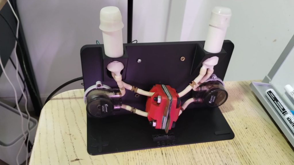
Over the past year, I’ve collaborated with my colleagues Kirk Smith, Sanli Faez, and Joshua Hauser on developing an open-source flow battery design and kit. Our aim is to make it feasible for most individuals to construct this flow battery with readily available parts that can be either purchased online or fabricated affordably. We’re targeting a price point below 1000 EUR, inclusive of the potentiostat, to ensure accessibility.

The kit encompasses all necessary components for constructing and utilizing a flow battery for research and development purposes. This includes the battery itself, pumps, electronic components for pump operation, potentiostat, tubing, reservoirs, and a jig for orderly arrangement. Presently, similar setups cost upwards of 9000 EUR, hence our aspiration for significant cost reduction.

A polypropylene FDM printed prototype being tested with Mn/Fe chemistry. This particular test was done without reservoirs, on close circuit circulation to easily detect any leaking.
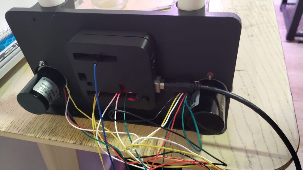
Image of one of our latest prototypes. This features polypropylene FDM printed reservoirs, a resin printed cell body and a PLA FDM printed jig.

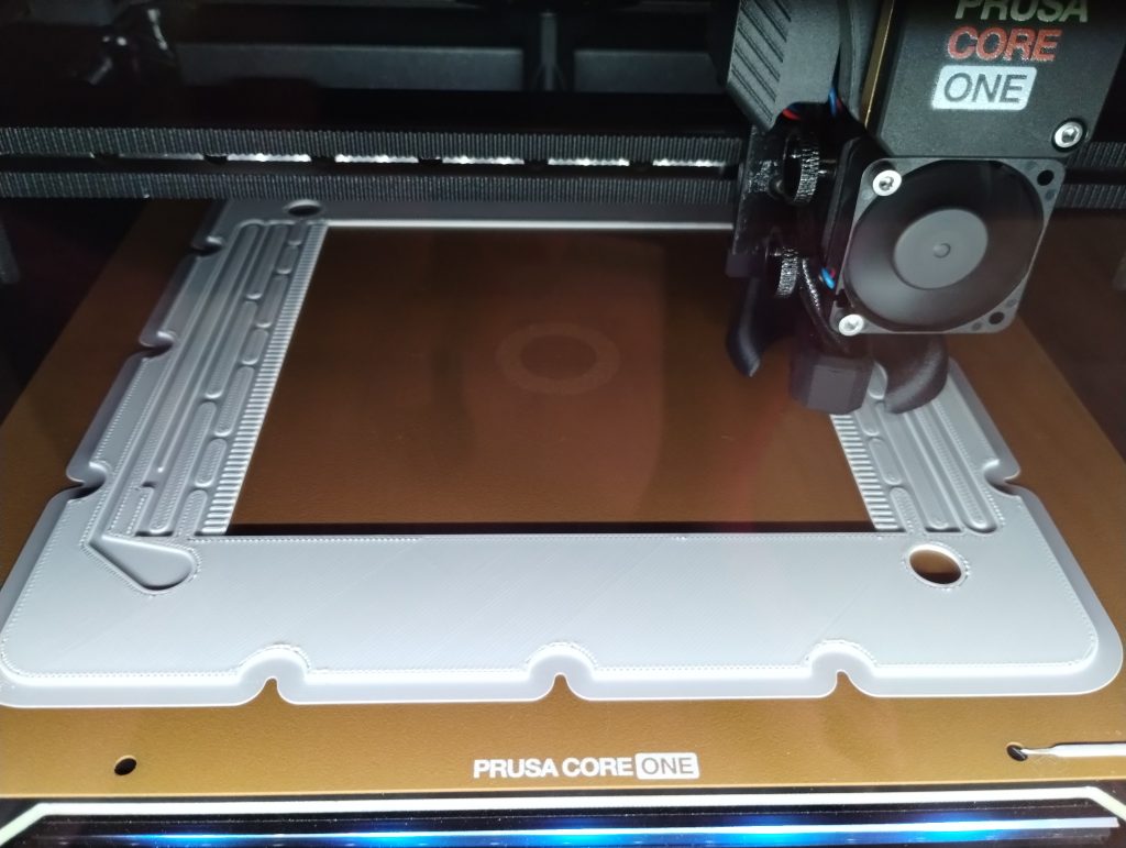
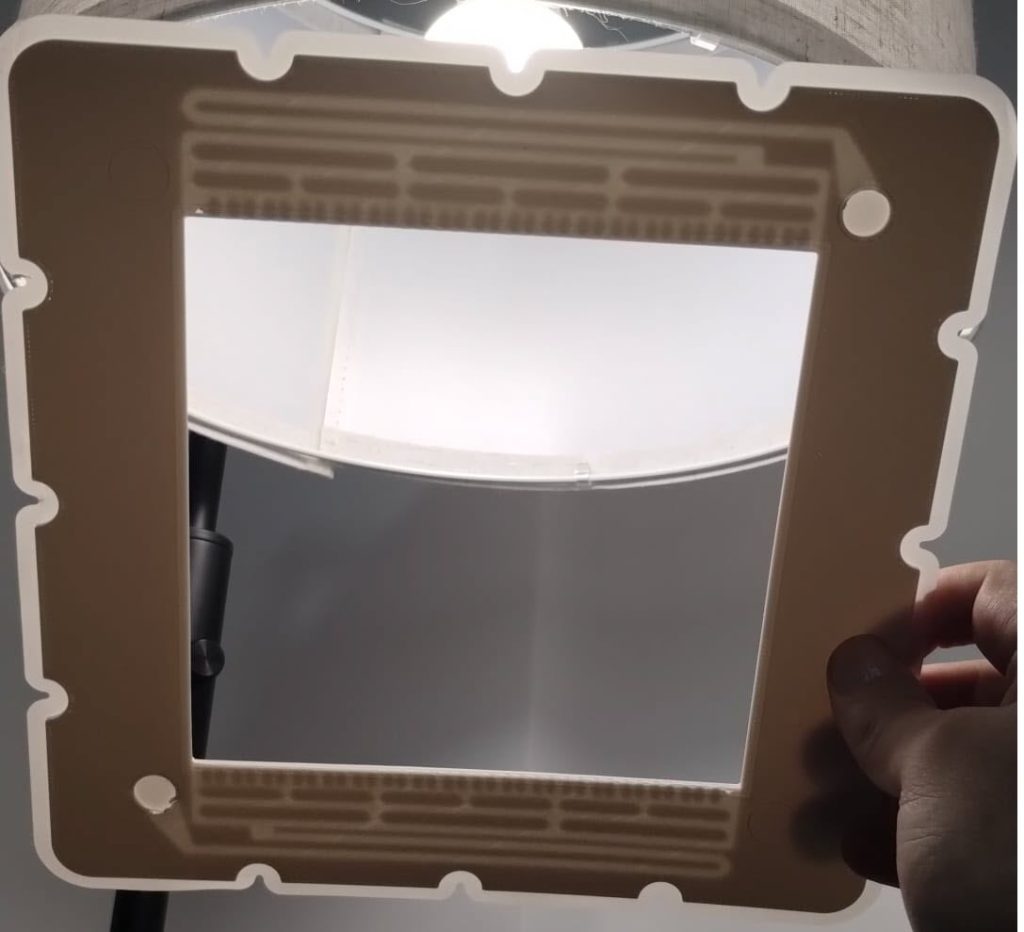
Throughout this endeavor, we’ve explored various fabrication methods for our designs, employing FDM and resin 3D printing techniques alongside traditional CNC fabrication. While all three methods are viable, our experiments indicate that the most optimal results are achieved through traditional milling.

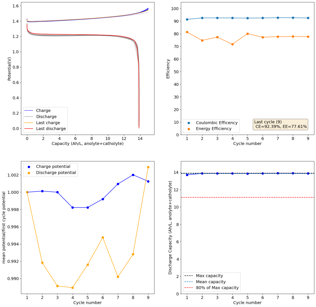
Charge/discharge cycle using photopaper separators and the Zn-I chemistry using the open source flow battery design.

Validation of our design involved utilizing a low-cost photopaper separator and Zn-I chemistry. We’ve achieved successful charge/discharge cycles at capacities ranging from 20-40 Wh/L. However, long-term cycling validation remains ongoing, as we’ve only been testing the final design for approximately a month.

Our design will be presented at the Flow4UBattery Event in Eindhoven, Netherlands, on April 8-9, 2024. You can register here for free, which also includes complimentary lunch (so please make sure you intend to attend if you subscribe). Day 2 of the event will feature a workshop where participants can assemble a flow battery themselves using the design from our kit. Additionally, we’ll be giving away 5 complete kits during the event, each including mystat potentiostats. We’ll also have a fully assembled kit doing cycling so that you can see the fully assembled kit in action!

After this event, we will look into selling these kits online, with all proceeds going towards the development of higher capacity kits with the objective of reaching an open source flow battery stack within the next 2 years. We will also be publishing the full designs and bill of materials online, so that anyone can create their own too!

A Zinc-Iodide flow battery using a matte photo paper membrane

On my last post, I showed the results of charging/discharging a flow battery using a ZnCl2+NH4Cl+KI electrolyte using 4 layers of Daramic as a membrane. However, while Daramic is a low cost material, it is not easily accessible for DIY testing at this moment. For this reason, I wanted to run some tests on materials that are easier to source than Daramic.

I looked for materials around my house that had similar porosity (0.1-5um). I tested several different papers that I had around but none of them worked very well. The porosity of most traditional printer papers is high, with most having 10-20um pore sizes. This means that you need many layers to prevent fast self-discharge from migration of the triiodide across the membrane. Additionally, the papers lost structural integrity quite easily.

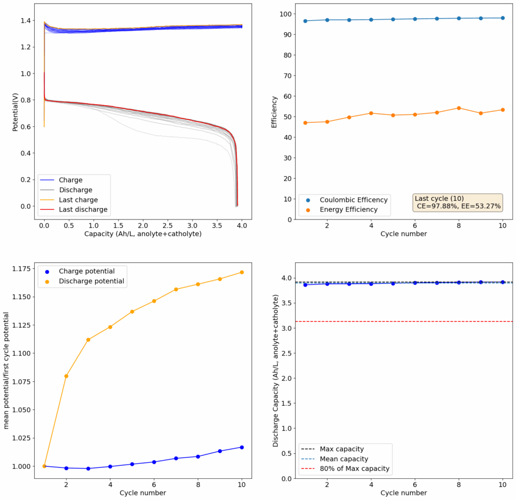
Test using a 2m ZnCl2 + 2m NH4Cl + 4m KI electrolyte at a current density of 20mA/cm2. Four layers of matte photo paper were used as separator.

Finally, I stumbled upon matte photo paper as a potential solution. This paper has much lower porosity with <5um pore sizes. Some of these papers might even have pore sizes that are below 1um. This is important for printing photographs, as low pore sizes implies that there is less bleeding of ink when it is applied to the paper, although ink needs to be applied much more slowly to the material (reason why printing with these papers is really slow).

For my initial test, I used 4 layers of matte photo paper. The paper does have a substantially higher ohmic resistance compared to Daramic, so I had to lower the current density to 20mA/cm2. I did 4 cycles of charge/discharge that you can see above (I only did 4 because the lower current meant cycling was quite slow). The CE of 87.54% and EE of 75.72% with a capacity of 33.8 Ah/L shows that photo paper is definitely a good choice for at least the short term cycling of these devices.

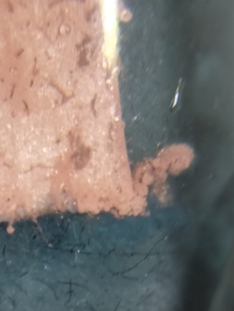
On inspection, the photo paper did not show any evident degradation although dendrite penetration happened just as much as it did with the Daramic separator. The separator was also completely black, fully permeated by the catholyte solution which contains triiodide in solution when charged.