I have recently been working on a project to create a DIY flow battery using Fe/Mn salts. The idea is to be able to achieve a close to or neutral pH system, with low cost salts, high concentrations of active species and good cycling ability. In today’s post I will describe some of my very preliminary results using a split cell system.
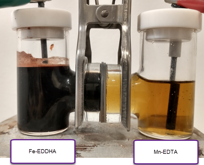
The image below shows you the experimental setup I am using. Both the right and left side contain graphite rod electrodes. The two chambers are separated by the DIY high permselectivity membrane I prepared using PVA/citric acid/phosphoric acid. The chamber on the left contains a solution of NaFeEDDHA from a commercial fertilizer source at a concentration of 0.05m + 3.5m of NaCl, while the cell on the right contains a solution with 0.05m of Na2MnEDTA + 3.5m NaCl. The pH was set to 7 using potassium carbonate (only a few milligrams were needed). Both chambers are stirred using magnetic stirring bars (tiny ones at 2mm).
The idea of these first experiments at low concentration was to put some charge into the system to observe if there was any precipitation of Mn oxides on the cathode, or any other noticeable side reactions. We can also determine if there is any self-discharge due to crossing of Fe-EDDHA over the membrane by seeing the color change on the Mn-EDTA side and tracking the potential. I also wanted to observe what the potential was after charging (predicted standard potential is around 1.2V).
It is worth noting that the separation between the electrodes is quite large and the electrode area is low, so there are expected to be very substantial ohmic losses in this type of configuration. This means it is not useful for charge/discharge cycle data. However we should be able to get some important information about the reversibility of the chemistry and the presence of any bad side reactions, as mentioned above.
The capacity of the system at this (15mL per side) configuration would be 20.1mAh. I charged it to 2mAh at 2.3V, which was able to introduce current at a rate between 700-800mA. After stopping the charging process, the potential dropped to around 1.1V fast and then very slowly from that point. It will take more charge for the potential to hold steady there, but this already shows the chemistry is working. Changing the electrodes for new graphite rods had the potential still holding at similar values, which means the potential is not due to any deposits on the graphite electrodes.
Despite the big charging over-potential – due to ohmic losses – there was no depositing of metallic Fe on the anode or the evolution of any hydrogen gas (no bubbling was observed). I also could not observe the formation of any MnO2 precipitate on the cathode. This therefore means that the Mn3+ is stable, at least in the short term, in the catholyte (as expected from literature experienced with Mn-EDTA).
Hi. Thank for you showing me the USB battery tester, this will come in handy for my upcoming test and review of the iron/copper-oxide Alkaline “Junkyard” battery. I don’t see this being mentioned or I missed it. So I thought I would drop by comment. It would be fun to monitor your findings as well if you decide to experiment with it.
Sources:
1. Artikle: https://news.vanderbilt.edu/2016/11/02/making-high-performance-batteries-from-junkyard-scraps/
2. Original research and supplemental: https://pubs.acs.org/doi/abs/10.1021/acsenergylett.6b00295
Thanks for writing. I likely won’t test this type of battery setup. The problem is really the anodizing process of steel. The steel anodization requires a 40V high current source, it also requires you to work with ammonium fluoride (fluorides are highly toxic and waste needs to be handled very carefully) and ethylene glycol. It also requires an annealing step with the sheets at 350C in an Argon+Hydrogen atmosphere. Performing these steps in a home environment is not easy to do, nor desirable as it would require handling of a highly combustible gas (hydrogen).
You might want to pursue a different steel anodization technique for nanostructuring that avoids NH4F and the annealing step. Like the one shown here https://pubs.acs.org/doi/full/10.1021/acsami.5b12107.
Also it is critical to note that the performance of these batteries was assessed based on the mass of active material (the nanoscale oxide coating on the electrodes) and NOT the full mass of the metal pieces used. If you made a total mass comparison, power and energy densities compared with lead acid will be 100x. times lower. Because of this, this is not a viable battery option in any reasonable sense. A good reason why this paper, written 6 years ago has only 11 citations in the literature up to date.
– Hi. The article you linked to is certainly a simpler process. I will take that into account and actually test that one instead. Cleaning Cu/brass with HCL can easily be substituted with Citric Acid and doing so, you are left with KOH and NaOH as the active etchants and some current.
– The reason I found the article I linked to was to substitute the NiOH which is difficult to get a hold of inside the EU unless one are a company. So even small experiments are difficult. So if anodized copper/brass can get me close to NiOH performance, I’ll take it.
– There is another interesting Iron electrode produced via a hot-press method which incorporate bismuth sulfide to reduce H2 evolution. This electrode has a Coloumbic efficiency of 96% and overall energy return of 80%.
Source: https://iopscience.iop.org/article/10.1149/2.034208jes
Once again, thanks for the alternative iron anodizing. Also following your work, its very interesting.
Thanks for your reply. It is worth noting that this battery is not the same or even analogous to a Ni-Fe battery. In Ni-Fe batteries metallic Fe is oxidized while a Ni+4 hydroxide is reduced to an Ni+2 hydroxide. In the case of the steel/brass battery, while the Fe can reduce to metallic Fe, the Cu/Zn oxides on the brass cannot oxidize further (a tale-tale sign of the lack of an actual galvanic pair is the lack of explicit mentioning of any cathodic reaction). This means that this does not work as a normal battery does (reason why its power density is 100x lower when considering total mass). The charge/discharge curves and power characteristics shown are actually more aligned with the behavior of a capacitor where there is some minor electrochemical contribution.
I would recommend not pursuing this, the electrochemical characterization is very misleading due to their choice of a minute mass for power/energy density calculations. In reality this is just not feasible for anything.
I am also in the EU, so you should be able to get everything I get to run experiments if you continue following my posts.
One more comment regarding anodizing steel. Was watching a video on YouTube [How to anodize steel] which is done in either KOH or NaOH solution and one of the surfaces and materials achievable is Fe3O4 or Magnetite. In other words, its is very likely that nano sized magnetite is what the is what the junkyard team was making or trying to make.
Thanks for your reply. So anodizing in regular KOH/NaOH solutions at lower concentrations does not produce nanostructured oxides. This is because the generation of high surface area oxide structures requires partial dissolution of the oxides formed, which is why ammonium fluoride is generally used. The fluoride dissolves some of the formed oxide to create nano structured materials instead of more compact films. To anodize steel and form nanostructures with NaOH you require very aggressive concentration, 10M, to be able to dissolve some of the oxides as ferrates.
I also modified my last reply to add some comments on the actual power/energy densities of these batteries. They calculated the energy and power densities of these batteries using only the active mass (a very small mass of the active oxide created during the anodization) and not the weight of the bulk metal. If you actually take the weight of the battery and compare it with the weight of a normal lead acid battery, the energy density is close to 100x lower. Looking at the experimental results this is not a feasible battery at all. A good reason why this paper, written 6 years ago has only 11 citations in the literature up to date.
Thanks Danielfp for your replies after I “hacked” your tread ;), they are greatly appreciated and you are probably correct regarding the FeCu oxide battery from earlier in our conversations.
Now, to cut a long reply short. One of the simpler chemistry’s that stood the test of time is the NiFe alkaline. If we look at standard battery’s incl Pb-acid, NiCd, NiMH, Li-ion, they have a relatively short cycle lifetime. In comparison, the NiFe is relatively simple and can be enhanced to return 46 W-h/kg with a C rate of up to 6C (Encell Technology Inc) with a cycle life greater than 5000. But regulations for obtaining nickel salts makes it difficult for a civilian to work with this battery technology. As an example, living in Sweden forces me to obtain a license and chemical suppliers which deal with nickel salts incl NiOH, only sell to company’s. NiFe is highly regarded as a very good solution besides the issues I mentioned
Not giving up per say, but I started looking at alternative chemistry’s and ZnBr popped up, but there we are dealing with zinc dendrites and fairly high self discharge. Gelion is still to release their performance data so we’ll see what they say about cycle life and self discharge rate.
If we return to your FeMn flow battery here, say it could be relatively stable at a nominal voltage of 1.2V and the referenced 40 Wh/L with a cycle life greater than 1000, then that is something one should seriously consider.
On that note, the test cell isn’t using any active pumps, so in reality, its more of a static battery .. 😉
Thanks for your reply. This is definitely not a flow battery yet, hence the title “towards” a flow battery. This type of experiment is done before full flow cell configurations are built to figure out if the chemistry is working correctly for the most part. Building a flow cell is a much more involved experiment, so that will likely take me around 6 months, if all the experiments I have scheduled go as planned.
If you’re interested in more accessible DIY battery technologies, I think Zn-MnO2 batteries would probably work better for you. My forum thread on DIY Zn-MnO2 should give you some ideas (https://diysolarforum.com/threads/my-adventures-building-a-zn-mno2-battery.32150/). I stopped working on this because I had to move to a new country and couldn’t take my lab stuff right away, but I was having some interesting results, including batteries that I was able to run for >1000 cycles (although at really low densities of around 3 Wh/L).
Good afternoon.
First of all, don’t stress, work on the project at your own comfortable pace and do everything you need to do.
I found the diysolarforum.com thread for this battery chemistry and joined the forum and in there mentioned that I want to contribute and now I have mentioned it here :). I am in no rush time wise since my need is 5 years or more away, but I am in a sort of rush to locate a chemistry that can replace the nickel while maintaining the longevity of the iron side of things and your Mn/Fe flow battery is certainly checking a lot of boxes. Since I need to learn more about flow battery’s, I clicked on Wikipedia’s page on Iron Redox Flow Battery and indeed, the cycle life is somewhere between 10-20k
The the neat thing about flow battery’s is that the current collector and channels for the flow can be made as one piece and if made of copper or aluminium (gold plated to be corrosion resistant against the saltwater), it will reduce the internal resistance which will aid in the battery’s C rating. – Also, I am sure that the performance needs and flow rate can be tuned such that the pumps doesn’t have to be on all the time but rather used occasionally to conserve energy. And if your cation exchange membrane contribute to a very low self-discharge rate, I think the premises for a friendly DIY battery is very high. So I might be in for the long run.
“We need cheap fusion reaction to power our future homes” … me looking at the person and pointing towards the sun and my solar panels and battery storage … 😂
(one day)
Thank for your replies and happy to have you along for the ride! The more the merrier!
Yara International ASA (Former Norsk Hydro) can supply me with Fe-EDDHA and Mn-EDTA, or as they are also called: EDDHA iron chelate (6% Fe) and EDTA manganese chelate (12.8% Mn). Can you pleas verify that these two would be appropriate ? – The links take you to the UK site for ease of understanding, but Yara is available in many other countries.
Scroll down to: Soluble chelated micronutrients: https://www.yara.co.uk/crop-nutrition/fertiliser/soluble/
Those two choices are acceptable.
Thanks a million 🙂
This is an excellent project, please keep it up! I found your site while looking for examples of open-source potentiostat/galvanostats. I am planning a similar experimental program, for the all-iron chemistry (with some new approaches to handle the HER). I just finished my PhD on flow batteries a year ago, albeit nonaqueous ones – I’m still convinced there are promising aqueous approaches, like these abundant transition metal salts. I’d love to chat sometime and trade notes, I am still getting my at-home lab equipment to start testing.
Thanks for writing Kirk! My resources are a bit limited, so it’s hard for me to do a lot of research at my house. To build the flow batteries I likely need 10k USD in equipment, so it might take a long time to advance here. Where are you located? I sent you an email, would love to chat.
Very nice. Have you thought of experimenting with a vanadium flow battery? I have toyed with that idea for a while.
Vanadium cells need to use very acidic electrolytes using sulfuric acid, plus Vanadium is quite toxic. For these reasons I do not want to run such experiments at my house.
Pingback: Problems with the Fe-EDDHA|Mn-EDTA flow battery system | Chemisting