I have recently been working on a project to create a DIY flow battery using Fe/Mn salts. The idea is to be able to achieve a close to or neutral pH system, with low cost salts, high concentrations of active species and good cycling ability. In today’s post I will describe some of my very preliminary results using a split cell system.
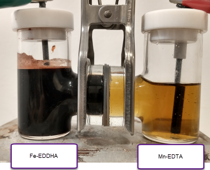
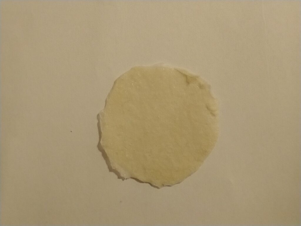
The image below shows you the experimental setup I am using. Both the right and left side contain graphite rod electrodes. The two chambers are separated by the DIY high permselectivity membrane I prepared using PVA/citric acid/phosphoric acid. The chamber on the left contains a solution of NaFeEDDHA from a commercial fertilizer source at a concentration of 0.05m + 3.5m of NaCl, while the cell on the right contains a solution with 0.05m of Na2MnEDTA + 3.5m NaCl. The pH was set to 7 using potassium carbonate (only a few milligrams were needed). Both chambers are stirred using magnetic stirring bars (tiny ones at 2mm).

The idea of these first experiments at low concentration was to put some charge into the system to observe if there was any precipitation of Mn oxides on the cathode, or any other noticeable side reactions. We can also determine if there is any self-discharge due to crossing of Fe-EDDHA over the membrane by seeing the color change on the Mn-EDTA side and tracking the potential. I also wanted to observe what the potential was after charging (predicted standard potential is around 1.2V).
It is worth noting that the separation between the electrodes is quite large and the electrode area is low, so there are expected to be very substantial ohmic losses in this type of configuration. This means it is not useful for charge/discharge cycle data. However we should be able to get some important information about the reversibility of the chemistry and the presence of any bad side reactions, as mentioned above.
The capacity of the system at this (15mL per side) configuration would be 20.1mAh. I charged it to 2mAh at 2.3V, which was able to introduce current at a rate between 700-800mA. After stopping the charging process, the potential dropped to around 1.1V fast and then very slowly from that point. It will take more charge for the potential to hold steady there, but this already shows the chemistry is working. Changing the electrodes for new graphite rods had the potential still holding at similar values, which means the potential is not due to any deposits on the graphite electrodes.
Despite the big charging over-potential – due to ohmic losses – there was no depositing of metallic Fe on the anode or the evolution of any hydrogen gas (no bubbling was observed). I also could not observe the formation of any MnO2 precipitate on the cathode. This therefore means that the Mn3+ is stable, at least in the short term, in the catholyte (as expected from literature experienced with Mn-EDTA).


