For Zinc-Bromine batteries, energy density is a key characteristic since these batteries are bound to be used under circumstances where the specific energy (Wh/kg) is not as relevant as the amount of space taken by the batteries to store a given amount of energy (like utility level energy storage). Given this fact, I wanted to explore how hard I could push the capacity of a Zn-Br battery to try to maximize its energy density.
I built a cell with a GFE-1 cathode pretreated with a 50% TMPhABr solution, used 16 layers of fiberglass separator (total cell height 0.53cm, total area 1.29cm2, volume 0.68mL), used a 3M ZnBr2 + 20% PEG-200 solution to minimize dendrites as much as a I could. I then tried to charge the cell to 30mAh, see what sort of efficiencies I could get. I used a current of 5mA since the 20% PEG content and highly loaded GFE-1 cathode both substantially increased the internal resistance of the device.
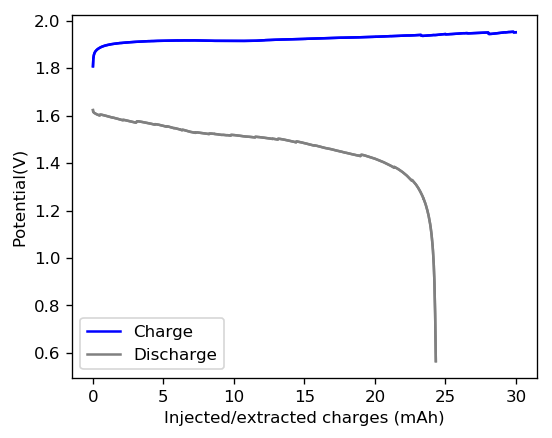
Given the results shown above, I was able to achieve an effective stored charge of 18.7mAh, which gives the cell an energy density of 43.76 Wh/L. This puts the battery above the values that are achieved for commercial Zinc-Bromine flow batteries (5.7–39 W·h/L). However not everything was as good as I thought, as the battery shorted during the second cycle due to the formation of Zinc dendrites. I was however very puzzled by the presence of Zinc dendrites at a 20% PEG-200 concentration, so I decided to open up the battery and peel the layers to see what was going on.
As you can see in the image below, zinc dendrites form predominantly across the first 3 layers of fiberglass separator, which means that the PEG-200 was indeed effective at preventing dendrite formation from advancing too much through the battery (without PEG-200 you would see a significant presence of dendrites all the way to the cathode). However there were some Zinc dendrites forming predominantly close to the edge of the battery and these progressed all the way to the cathode material, although it is very hard to see their presence without magnification within the last couple of layers.
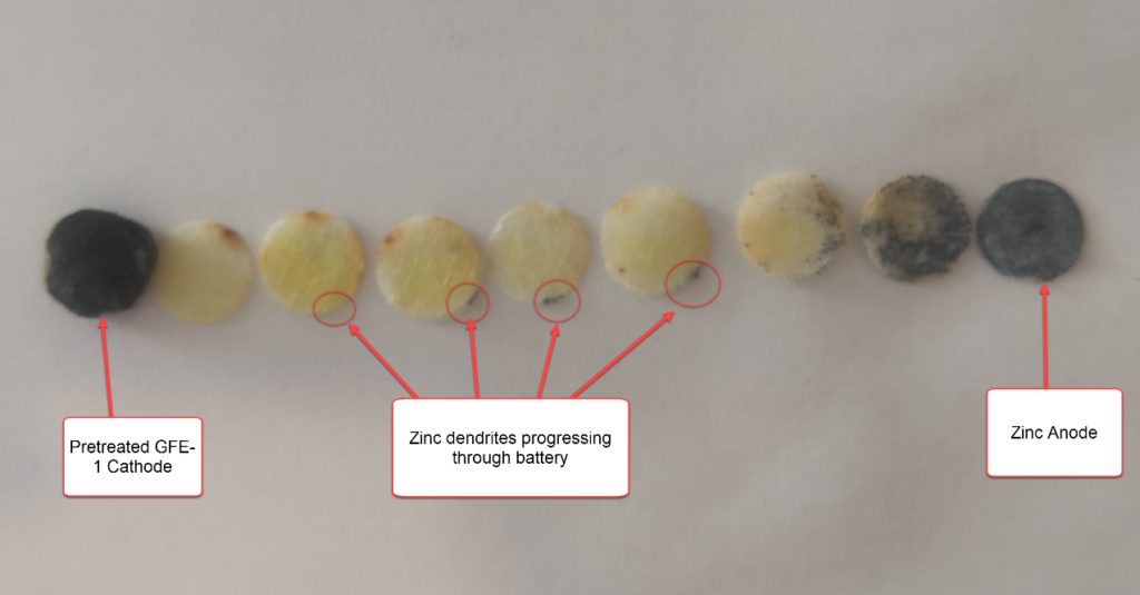
The fact that I am using a Zinc anode that is cut from a 0.2mm sheet with a perforator might have something to do with it, as the Zinc is bound to be extremely sharp at the edges – therefore high surface area – due to the cutting process. This is the perfect spot for the formation of dendrites and – due to the smaller amount of electrolyte at these points – could easily lead to the formation of dendrites moving through the battery, which is what we have observed. This also happened at a point where the Zn anode was particularly sharply cut, which further reinforces this hypothesis.
In order to see if the Zinc anode and the way it’s cut has a lot to do with this fact I have decided to repeat the above experiment using the graphite electrode as anode – without the presence of any Zinc anode – which should show if zinc dendrites are able to form all the way to the cathode in the presence of large concentrations of PEG-200. If Zinc dendrites do not form in this case, I will move to the use of graphite for the anode material from now on.
Have been too busy to check in for awhile and you’ve made some impressive progress. I’m not surprised the issue of “orphaned” perbromide occurred, as any migration of Br from the cathode will result in discontinuous regions as it reacts with the complexing agent later. Have you found any relation between charge rate and orphaned perbromide? I would suspect higher charge rates would result in more free Br that will end up lost into the separator.
Is the yellow in this picture solid perbromide in the separator or is it the natural colour of the fiberglass?
If the sharp edges of the anode are enough to encourage dendrite formation, then I suspect ultimately any form of zinc anode will eventually result in dendrite growth after enough cycles. I’m interested to see the results from an inert anode. You will lose the ability to replenish zinc from the anode but gain the ability to refurbish the anode via deep discharge, theoretically putting all the zinc back into solution (unless some zinc separates from the plate and becomes orphaned as well)
The whole dendrite issue reminds me of NiCd “memory” which is caused by coarse growth on the cadmium plate, which can puncture the separator as well. The solution as you know is regular deep discharges to clean the plate. We also used to apply very high current pulses to shorted NiCd cells to destroy dendrites that had connected the plates, resulting in up to a year of continued use afterwards.
It might turn out this cell may also require periodic deep discharge to combat dendrite formation simply as a matter of operation.
Thanks again for commenting Alex!
I haven’t tested how charge rate affects the perbromide migration but from dismantling different batteries I can tell that this problem is proportional to the amount of TMPhABr loading on the cathode. Cathodes pretreated with 50% TMPhABr tend to show significantly less perbromide migration, although this is at the cost of higher internal resistance for the cell.
The separator is naturally white, this is likely either perbromide or bromine that has migrated through the separator.
I am testing a 20% PEG solution as well to see if this has the ability to prevent dendrite formation, even those that form at the edges. Sacrificing some voltaic efficiency might be worth it if this problem can be completely eliminated or at least suppressed long enough to allow for 200+ cycles.
It is in fact pretty reminiscent of NiCd memory. Commercial Zn-Br flow batteries have to indeed go through cycles of forced deep discharge across low resistances to allow for all the Zn dendrites to be eliminated in order to increase battery life. It would be great if I could get rid of this problem or at least reduce it enough to make a static battery of this type more viable.
So this cell only includes TMPhABr initially incorporated into the cathode and not dissolved into the electrolyte? I suppose it will migrate into the electrolyte with time and form a gradient, but I wonder if initially this allows some Br(l) that is formed on the surface of the cathode to migrate into the separator and escape.
You say you are testing a 20% PEG solution as well, but it looks like you already used 20% PEG in this cell? If it works, PEG is a good solution being cheap and readily available even if it does result in increased resistance or some loss of efficiency.
Increased internal resistance is an issue I wouldn’t worry too much about at this stage compared to low cycle life or need for deep discharge due to dendrites. Lithium ion batteries had quite high internal resistance for years before we got to the cells we use now. A fairly high resistance cell can still be useful while being improved incrementally, and low C-rate lithiums are still common and commercially viable to this day.
I wonder if the orphaned perbromide issue can be solved simply by using gravity to settle free bromine and perbromide crystals onto the GFE-1 cathode. If you use a coarse glass/PTFE mesh separator rather than fiberglass wool, and orient the cell vertically with cathode on the bottom, any perbromide crystals that form outside the felt should not get caught in the separator and thus fall onto the surface of the cathode, coming into contact so they can be reduced. Any small zinc fragment that becomes detached will also fall into the bromine region where it will react and return to solution.
Of course this might make it a little tricky to get the electrolyte into the cell. I’m not sure how the Swagelok cell is loaded with electrolyte but it kind of looks like you wet the fiberglass separator and then compress it together?
Thanks again for your comments! Let me answer your questions:
The TMPhABr is incorporated into the cathode and not dissolved, but its solubility is incredibly low in the highly concentrated ZnBr2 solution. I couldn’t get 20mg of TMPhABr to dissolve in 10mL of 3M ZnBr2, so some sort of gradient might form through time, but it is not bound to be very big given that the maximum possible concentration of dissolved TMPhABr is very low.
PEG-200 works great to reduce dendrites, it reduces them very efficiently but not completely, which is problematic given some edge effects I’ve been encountering. In my latests experiments I am trying even 30-35% PEG-200 to see if this makes it even harder, but maybe at this point it will be more effective to add a support electrolyte to prevent these edge dendrites instead (as ion depletion due to the charging process seems to be causing issues with ion migration). I agree with you that high internal resistance is a tradeoff we can make if it leads to better cycle life or eliminate the need for deep discharge.
I fill the cell by putting electrolyte on top of the cathode, it then gets wicked by the cathode and separator all the way to the anode. Your proposal to use a separator that does not wick the solution is interesting, although this might lead to some problems within the Swagelok cell geometry since the electrodes do not seal extremely well and electrolyte could in theory just “leak out” by gravity if it is not held in place by some separator. This is something I might try if the dendrite issue becomes insurmountable using a fiberglass separator of this type. The PTFE mesh seems particularly attractive.