Monthly Archives: September 2020

Zinc Bromine Batteries: Initial thoughts about a practical battery

During this past week I have been experimenting and thinking more about Zn-Br batteries and how a real practical battery would look like (how it would be built and what its characteristics would be like). Let’s imagine we have found a complexing agent that can be used in highly concentrated ZnBr2 solutions. What would a prototype battery look like and how much would it cost?

The first thing we need to consider is the geometry to build such a battery. Single-cell batteries for Zn-Br chemistry are impractical due to the limits that would impose on current density – and it’s not the 19th century – so the ideal battery would probably follow a configuration similar to modern lead-acid batteries, where multiple cells are put together to achieve better results. The simplest way to do this is to stack materials next to each other within a box, then flood the box with the desired electrolyte solution.
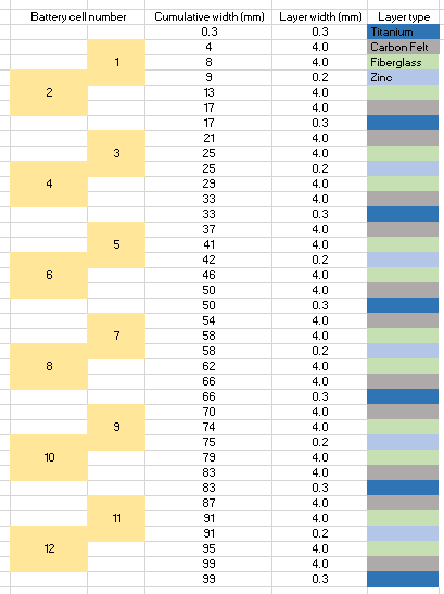
Proposed stacking of layers for a battery built in a 101x54x55mm project box. Note that the cells are laid horizontally (left to right) . Fiberglass separator thickness should be increased so all contents fit tightly inside the box.

In a 101mm x 54mm x 44mm project box you could fit a volume of around 237mL. If we decide to use a very porous carbon felt electrode – which I have experience with – with titanium current collectors, glass fiber separators and zinc anodes, we would create a cell configuration like the one showed above. This would occupy the entire cell with either separator, current collector, anode or cathode material. Given that the materials used take little real volume, as they are either very porous or very thin, I’m going to assume the solution volume we will fit will be equal to 200mL, which is realistic given the characteristics of the materials.

If we use a 2M ZnBr2 solution, this would give a maximum theoretical energy of 40Wh. If the cells are all connected in parallel, this would give us a battery with a voltage of 1.85 at a capacity of 21.6 Ah. The battery would be charged at a constant current of around 2.85A, although depending on the actual kinetics this might need to go down to even 285mA. In the above design you actually have only 6 cells that are each equal to 2 normal cells connected in parallel – as they share a current collector in the cathode – so connecting these 6 in series would give you a voltage of 11.1V with an expected charging current of 475mA.

The main caveat of the above design is that it uses a 2M ZnBr2 solution, assuming we can find a complexing agent that forms an insoluble perbromide that can be in the initial formulation at a concentration equal to at least the same as the ZnBr2 then this should be no problem. After a lot of research about the solubility of perbromides and organic ammonium salts I believe this might be possible using trimethylphenylammonium bromide, but such a complexing agent has never been tried! The 200 mL of solution used here would use 90.07g of ZnBr2 and 86.45g of TMPB.

Note that this configuration would certainly not work without a complexing agent that precipitates the tribromide formed. Without it the bromine would pool at the bottom and discharge the cell – in a horizontal configuration – or just sink and discharge the cell in a vertical configuration.

Cost (USD)ItemURL
3Project boxhttps://www.allelectronics.com/item/mb-132/abs-project-box-3.97-x-2.12-x-1.72/1.html
45Carbon felthttps://www.ceramaterials.com/product/gfe-1-pan-graphite-felt/
10.99Fiberglass tissuehttps://www.amazon.com/Multipurpose-Fiberglass-reinforcing-waterproofing-membranes/dp/B0719KWMJ7/ref=sr_1_5?dchild=1&keywords=fiberglass+paper&qid=1600038562&sr=8-5
11.49High purity Znhttps://www.amazon.com/99-9-Sheet-Plate-Metal-140x140mm/dp/B086FGDW83/ref=sr_1_5?dchild=1&keywords=Zn+sheet&qid=1600038696&sr=8-5
9.01Zinc BromidePrice with shipping confirmed from Alibaba vendor
19.99Titanium foilhttps://www.amazon.com/0-3mm-200mm-300mm-Titanium-Purity/dp/B07G8YYPFV/ref=sr_1_2?dchild=1&keywords=titanium+foil&qid=1600040029&sr=8-2
18.85TMPBPrice with shipping confirmed from Alibaba vendor
Potential materials used to construct a prototype Zn-Br cell

Using all the materials above, the cost of building such a prototype would be in the order of probably 120 USD. Probably around 200 USD after you add shipping for everything. In reality this cell is also unlikely to yield 40Wh and will most likely be in the vicinity of 20Wh if everything works as expected.

It is also important to note that an ABS project box like the one above is a risky first-choice, given that ABS can adversely react with elemental bromine, so a PTFE project box would – although much more expensive – be a safer choice for a prototype. By the time I build something like this, I hope I have already established that TMPB forms insoluble enough perbromide salts under my much more controlled Swagelok cell conditions.

Note that I am still far away from executing something like this! Currently I am even far away from testing a TMPB cell, but I wanted to write this blog post to condense all this theoretical research and serve as a referring point for me or others in the future.
Zinc Bromine Batteries: Can they really be that good?

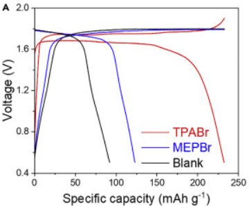
In my quest to study Zinc-Bromine batteries, I have been diving deep into this 2020 paper published by Chinese researchers, which shows how Zn-Br technology can achieve impressive efficiencies and specific power/capacity values, even rivaling lithium ion technologies. I’ve found some important things when studying this paper, that I think anyone looking into this technology should be aware of.

An example of specific capacity values for different cells measured by the Chinese researchers.

First, let’s talk about the specific capacity values found within this paper. Usually the cells in the study would be charged to a specific capacity of around 500 mAh/g, with Coulombic efficiencies greater than 99% in some cases. The cell used has a diameter of 0.5 inches – which gives us an area of around 1.29032 cm^2 for the electrodes – with the capacity per area at 1.5 mAh/cm^2. This is pretty amazing, because it means we are getting 1.5 mAh out of 3 mg of active material. Wait, what?

The researchers are pretty clear in mentioning that they calculate the specific capacity values given the weight of the cathode but, what they fail to mention explicitly, is that this is not the weight of the entire cathode material but merely the conductive active material within the cathode, which has a carbon loading of 3mg per cathode piece. The real cathode does not weight 3mg, it weights significantly more – probably an order of magnitude more – given that the cathode is prepared using a binder in an 8:1:1 proportion with the carbon sources. This also does not count the weight of the electrolyte or the weight of the anode.

Granted, the above approach is not uncommon in battery research – reporting only capacity values of active materials – but in this case, in the real world, it’s not like you’re going to be getting 250 mAh/g of battery, you’re likely going to be getting a lot less. In the case of the specific power/energy values the researchers take into account the mass of electrolyte and complexing agent (ZnBr2 and TPAB) but they do not account for the mass of the separator, anode, or other materials.

Specific power/energy values published on the paper

The unfair and potentially misleading part about this is that they are comparing a very partial weight of their Zn-Br system, with the actual values for specific energy and power that have been measured for actual production Li-ion systems. We know of commercial Li-ion systems with specific energy values of 150-250 Wh/kg where that is delivered per actual kilogram of actual battery (including packaging and everything else).

Realistically a Zn-Br fully built battery is likely to have a specific energy way lower than what is published in this paper. So – not very surprisingly – realistic battery systems built with this technology will likely have an energy and power more on the low end of what current Li-ion technology has to offer, although they are bound to be superior to current Zn-Br flow battery designs.

The paper and Zn-Br technology are still extremely interesting – at least to me – because of the high efficiencies, way lower discharge rates, higher specific energy/capacities and other advantageous properties over traditional Zn-Br flow batteries, but they are unlikely to be a game-changer in the energy industry. As most of the time, researchers want to make their numbers look as good as they can within the general practices of the field and battery research is not the exception. I’m not saying that the researchers are being unethical or lying, just that the reader must be aware of how researchers report these numbers and how they compare to what you actually get in final products.

With that said, the confusion from how specific capacity/energy/power are measured in battery research is not without controversy. With some important efforts going on (see here) to try to create clearer standards within the field to avoid confusion.

Zinc Bromine Batteries: Think about the electrodes!

In order to study the chemistry of Zinc-Bromine batteries I have been using a swagelok cell that I bought from China that has a central Teflon body with stainless steel electrodes. This has been problematic due to the reactivity of these electrodes with the elemental bromine and tribromide salts produced in the battery, requiring the use of some “improvisation” in order to make the batteries work.

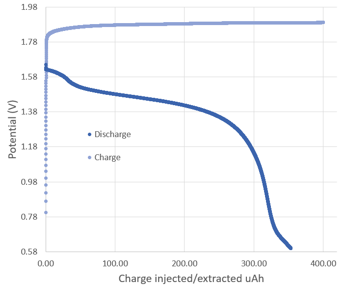
Charge/Discharge curve of a Zn-Br battery built using a zinc anode, carbon felt cathode, fiber glass separator and 0.5M ZnBr2+ 0.2 TBAB electrolyte in a swagelok cell with stainless steel electrodes covered with conductive HDPE.

To be able to generate the necessary chemical reactions without interference from the stainless steel I have coated the electrodes with some conductive HDPE I have, which has a relatively high volume resistance of around 10K ohm. The charge/discharge curve above shows you the type of measurements I have been able to achieve with this setup, with the above curve having a Coulombic efficiency of 88%.

This is lower than what I could achieve with the copper anode I was using previously (which gave me around 96%), but note how the charging voltage is lower and the discharge voltage higher, meaning that the overall energy efficiency is significantly better (around double). This is however not because of the zinc anode, but because with the conductive HDPE now covering both electrodes, I have now been able to tighten the cell more and achieve a lower overall internal resistance.

However the still relative low energy efficiency and voltage drop when going from charge to discharge are still pointing to significant sources of efficiency loss, possibly from the 10K ohm resistance that the conductive HDPE is giving. The weird shapes at the beginning and end of the discharge curve are also pointing to more than one chemical reaction happening, probably because the electrodes are still somehow interfering with the chemistry (maybe some micro holes in the conductive HDPE at points of stress are exposing the electrodes underneath). For this reason I have decided to get graphite electrodes for the Swagelok cell, which I will build from these 0.5 inch diameter graphite rods I found.

I am also going to change the current carbon felt cathode for carbon paper electrodes – which are on the way – but I will refrain from using the paper until I can perform some tests using actual graphite electrodes that are guaranteed to be free of any pesky side reactions, with way less resistance than this conductive HDPE.

Zinc Bromine Batteries: Current battery and experiments to follow

This week I published a post about my first success in the making of a Zinc Bromine battery, this first battery had a Coulombic efficiency of at least 96% and was able to show the expected charge/discharge curves, which I hadn’t been able to see before. In this post I want to talk about some of the problems I have found and the experiments that will follow to attempt to fix them.

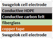
Current structure of my battery. The cell also includes around 80-100uL of a 0.5M ZnBr2+0.2M TBAB solution.

The structure of my current battery is shown above. The first problem I have run into are side reactions due to my use of copper tape as the anode used for zinc plating in the batteries. When I discharge the battery I seem to inevitably get some Cu oxidized and into solution, which is affecting the chemistry of the battery as a function of time. This means that I am losing a lot of coulombic efficiency and my charge/discharge curves are starting to show unwanted side reactions. I will be trying to replace this copper tape anode with a conductive HDPE covering plus a zinc anode to prevent any of these side effects.

The second problem comes from the use of a conductive carbon felt cathode that is pretty heavy (500mg per electrode used in the Swagelok cell) which means that my specific capacity is currently in the 0.5-1 mAh/g of cathode material, when ideally I should be seeing specific capacities in the order of 100-500mAh/g. The battery is already very efficient at using the electrolyte though as the maximum theoretical capacity of it is in the 0.01mAh/uL, given how much zinc and TBAB there is inside of it.

I have ordered an assortment of carbon paper materials (see it here) so that I can test whether these will offer me equivalent power storage with a significantly lower mass. I also ordered the MGL 190 carbon paper (see here) which seems especially promising given that I will be able to build a cathode weighing just 11mg for this area. This should allow me to reach much higher specific capacities if I’m able to sustain the same total capacity for the cell.

When I fully open the cells after going through a full charge cycle I do not observe any accumulation of yellow TBAB tribromide within the interior of the carbon felt electrode. This is telling me that whatever storage is happening is probably only going on within the first few microns of the cathode materials, meaning most of the cathode materials is actually being wasted and not being used for charge storage.

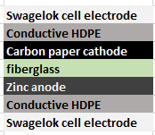
This is the new battery structure I’ll be moving to this week after I get the zinc anode and carbon paper materials.

Another problem with the carbon felt is that it has a lot of “loose hairs” that “sneak” into the porous fiberglass separator and cause shorts between the anode and cathode unless I use 4-6 layers of fiberglass I use (which is sadly pretty porous). This substantially increases the internal resistance of the battery and the hairs, although shorting the battery to a much lesser degree, may still be causing an incredible amount of self-discharge given that they do provide significantly shorter paths between the battery anode and cathode materials.

Getting rid of all copper, changing to a zinc anode, covering both anode and cathode with conductive HDPE and changing from a carbon felt cathode to a carbon paper cathode may all be moves that should help me greatly increase the performance of this battery. Stay posted for some further updates!

Zinc Bromine Batteries: First success!

In my first article about zinc-bromine batteries I discussed why these batteries are gaining interest and how some recent articles point to their potential use as reliable and cheap batteries, especially for large scale applications. After building my own DIY potentiostat/galvanostat, I wanted to use this technology to characterize home-made zinc-bromine batteries and experiment with their chemistry.

One of my initial attempts at a Zn-Bromine battery using carbon felt electrodes as both anode and cathode. Trying to charge the battery at 1mA/cm^2 never got above 1.32V and potential declined after time.

My previous article also mentioned some of my first attempts at building these batteries, which were mostly failed attempts due to the complexity of the battery builds. Even though I was able charge the batteries a little bit – and obtained relatively high Coulombic efficiencies when injecting a small amount of charge – I was never able to sustain potential values close to the expected 1.6-1.8V of the zinc bromine system. Always topping up at around 1.3-1.35V as shown in the image above, when trying to inject charges at 1mA/cm^2.

A huge problem of my first set of designs was a complete inability to adequately reproduce my batteries. The electrode construction was very complicated and every battery I tried had slightly different geometry and different amounts of electrolyte within their construction. In order to standardize the study I decided to change to a Swagelok cell construction (which I bought from China here). I bought a cell and got it delivered to the US within one week.

Button Cell Swagelok-Type Cell for Cell Testing
These are the Swagelok cells I am using to build my batteries now. These cells have an inner diameter of half an inch.

Although the Swagelok were supposed to make things easier, I started to face issues with the electrode material of the cells being reactive towards the bromine generated within the battery charging process. In my initial attempts using a carbon felt electrodes and a fiberglass separator, the stainless steel electrodes in the cell – which are inevitably exposed to the solution – were getting corroded away by the generated bromine and tribromine salts.

I was finally able to surmount these issues by covering the Swagelok cell electrode pieces with conductive HDPE, basically by wrapping the electrode with it and then inserting it within the Swagelok cell. Using this method I was able to produce my first successful Zn-Br cell using a tetrabutylammonium bromide (TBAB)/ZnBr2 solution (0.25 and 0.5M respectively) , a copper electrode for zinc reduction a fiber-glass separator and a carbon felt electrode for the tribromide depositing.

Charge/discharge curve of my first successful cell. I charged the cell to 500uAh and then discharged it until it reached 0.5V. This process was carried out at 1mA.

The image above shows you my first successful charge/discharge curve. To the best of my knowledge, this is the only example available online for experimental data of a TBAB/ZnBr2 cell. The Coulombic efficiency of the above cell was 96%, which is great considering this is the first successful one I have built. The cell used around 80-100uL of solution and 4 layers of fiber-glass separator (see my previous post for links to these materials).

I am still facing some issues related with the cutting of the separator/electrode materials to place within the cell (I have bought a 0.5 inch cutter which should make this way easier) and I am also going to try using a zinc electrode for the zinc plating, which should make things easier. I also want to see if I can get a better non-reactive conductive coating for the cell electrodes, since the conductive HDPE I am using has a quite significant resistance. Things are looking up though!