Since 2019, several groups with Chinese authors have published papers describing batteries using a Cu/Mn chemistry (1, 2, 3). This chemistry is very interesting as it has very cheap chemicals (just copper sulfate, manganese sulfate and sulfuric acid) and doesn’t seem to require any significant electrode preparation. The papers use either carbon cloths, carbon felts or copper plates, all with similar results. However, this chemistry is not as simple or as easy to reproduce as they make it seem. This blog post covers my attempts at reproducing these results.
To reproduce these findings I used 3mm thick carbon felt, celgard 2500 as a separator (as tested in reference (2)) and graphoil as current collector material. I also chose an area of 1cm2 in order to minimize material use and simplify calculations. I also treated the felt with a blow torch to improve its wetting abilities, by holding it in front of the torch for 10 seconds per side. I bought copper sulfate heptahydrate, manganese sulfate monohydrate and 15% sulfuric acid from laboratoriumdiscounter.nl. For the electrolyte I prepared a solution containing Cu 0.8M, Mn 0.8M and 0.8M H2SO4. The cell was immersed in 10mL of electrolyte. Given that this is a static battery that deposits MnO2 on the cathode and Cu on the anode, capacity should be limited by electrode volume and not by the volume of solution.
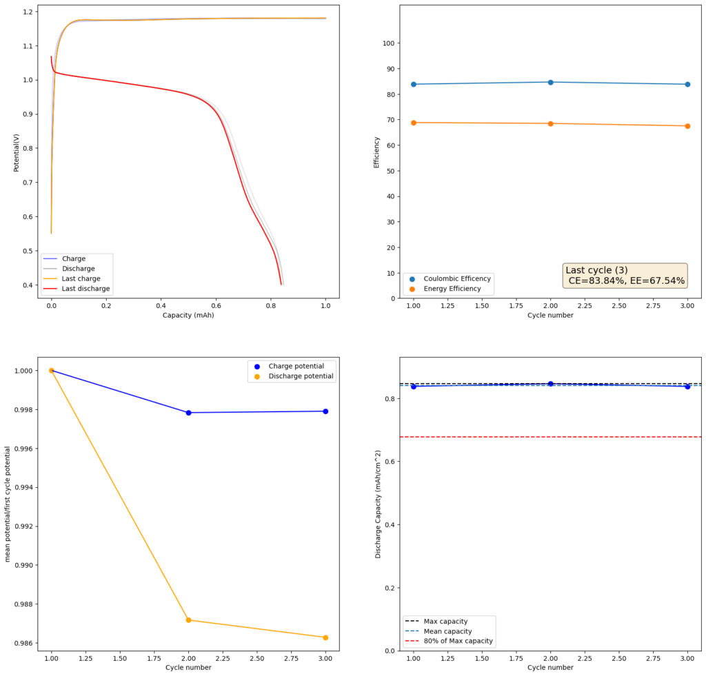
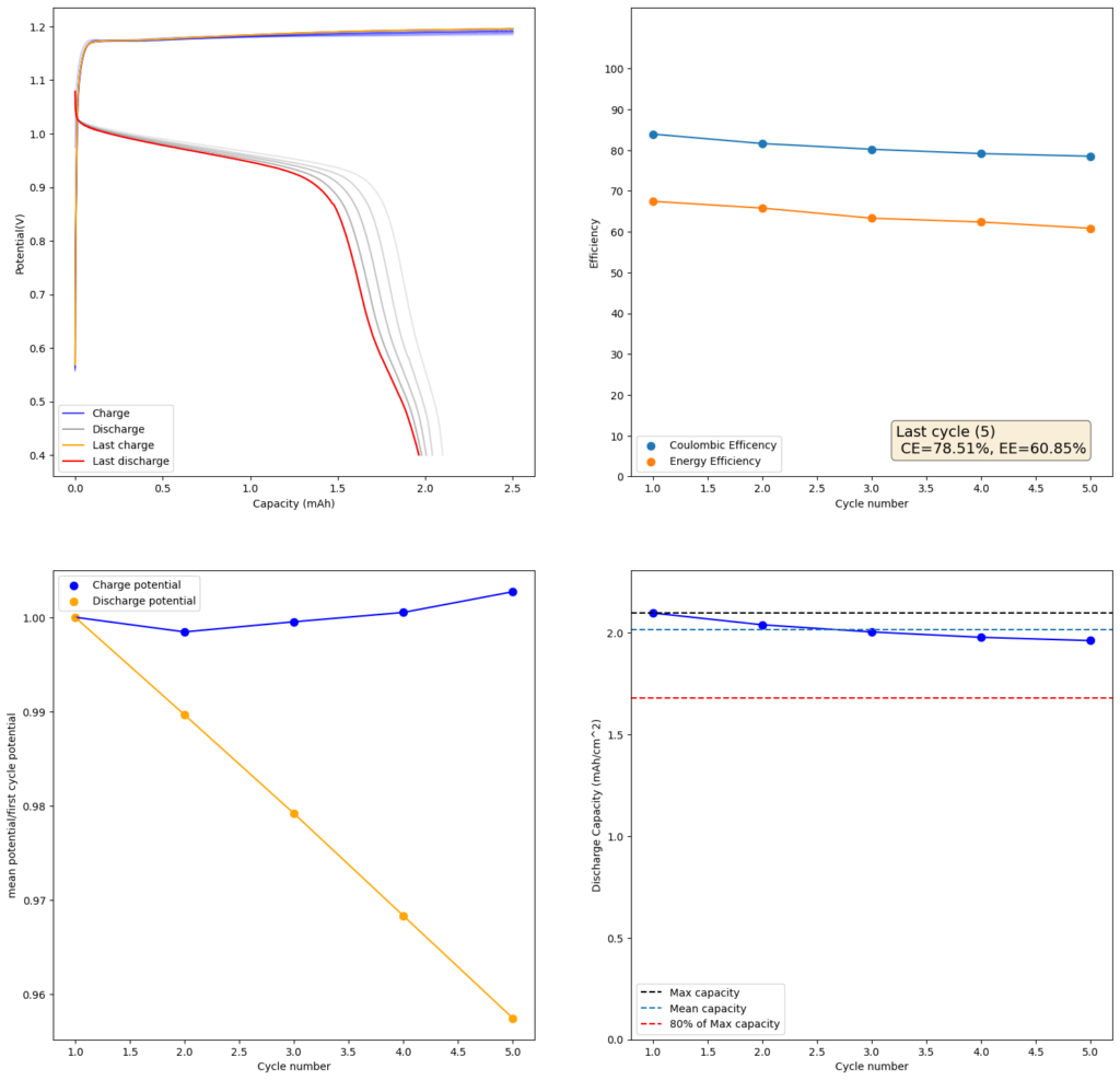
At low capacities, the battery behaves as shown in the figure above. The CE of the battery is significantly below 100% (~84%) and the energy efficiency is also quite low (~68%). This contrasts with the published literature which often shows CE efficiencies above 90% and energy efficiencies above 70%. I significantly increased the charge to 2.5mAh (4.16Ah/L), which showed a significant decrease in CE, EE and capacity with cycling. Specifically the discharge voltage started decreasing substantially with cycling.
Trying to go to even higher capacities (10mAh), as exemplified in paper (1) which shows values of up to 50mAh/cm2, I got the results showed below. There are very fast decreases in both CE and the EE, with the starting CE being slightly above 85% but dropping aggressively from that point going forward. In contrast with the lower discharge rate experiments, in this case the charging voltage did deteriorate aggressively as well.
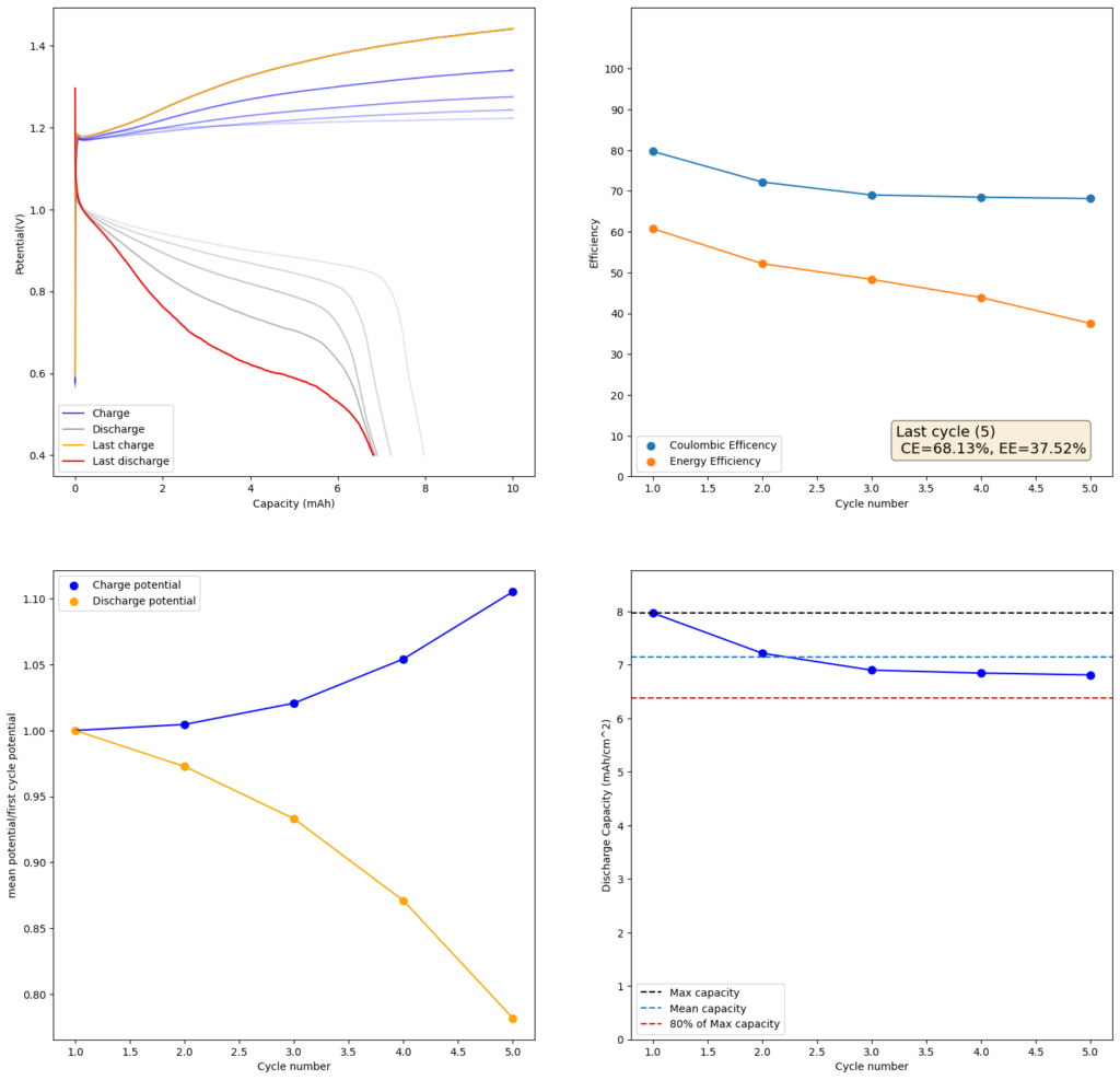
Charge/discharge cycles. Charge was done at 10mA/cm2 to 10mAh, discharge was done to a voltage of 0.4V. Total volume of the electrodes is 0.6mL. Highest discharge charge density is therefore around 13 Ah/L.
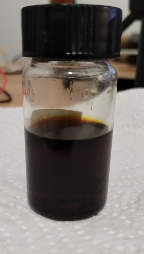
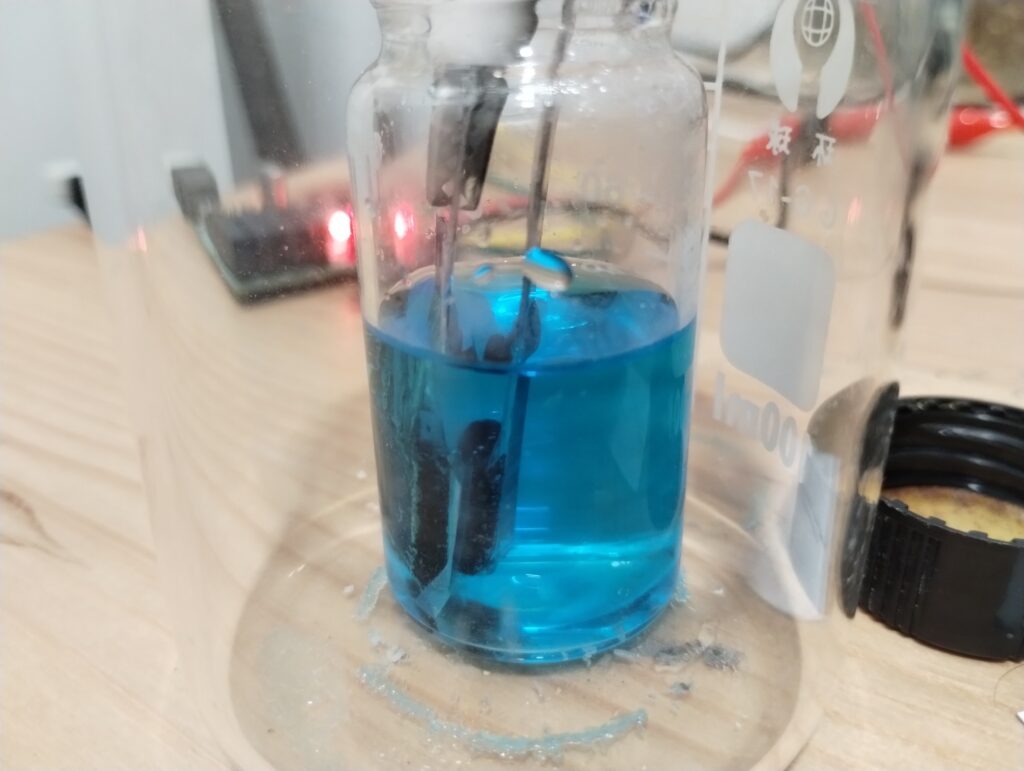
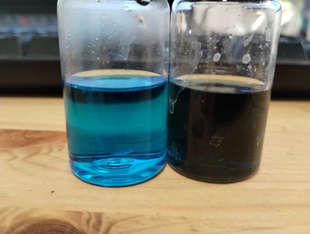
The electrolyte also shows significant signs of decomposition. The image below shows you a comparison of a pristine vs a cycled electrolyte. You can see how the cycled electrolyte becomes extremely dark, due to the presence of MnO2. This is confirmed by addition of ferrous sulfate, which immediately makes the liquid clear up (as Fe2+ is able to reduce MnO2 to Mn2+). The MnO2 is formed away from the electrode because of the formation of Mn3+ which migrates away and then disproportionates into Mn2+ and MnO2. This explains why there are significant loses in the CE as a function of charging, both due to Mn3+ disproportionation and self-discharge caused by Mn3+ migration into the anode.
The publishes papers make it seem as though this chemistry is extremely straightforward and reversible, but the facts of Mn3+ formation and disproportionation heavily complicate this approach. It is therefore puzzling to me how the results of these researchers were produced, especially the ones in (1) as their setup uses flooded cells us well, even in the complete absence of any separator. I made similar attempts using copper plates as anodes, 0.4M, 0.5M and 0.6M sulfuric acid and 0.5M, 0.8M and 1.2M Manganese sulfate solutions but couldn’t find any differences in the basic results, the only difference being that current densities needed to be much lower when a copper plate was used, likely due to the much lower surface area.
Let me know if you have any ideas about what I might be missing in the construction and testing of this Mn/Cu chemistry.